The Mustang Forum for Track & Racing Enthusiasts

Taking your Mustang to an open track/HPDE event for the first time? Do you race competitively? This forum is for you! Log in to remove most ads.

  • Welcome to the Ford Mustang forum built for owners of the Mustang GT350, BOSS 302, GT500, and all other S550, S197, SN95, Fox Body and older Mustangs set up for open track days, road racing, and/or autocross. Join our forum, interact with others, share your build, and help us strengthen this community!

S550 HPDE Prep - Need advice

This site may earn a commission from merchant affiliate links, including eBay, Amazon, and others.

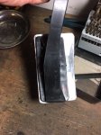
This is what I’m using for my backer plates...top piece is a backer plate I previously used on my ‘07 BMW Z4. Bottom piece is the same, after a bit of surgery. I was able to attach it using the two bottom bolts that were intended for attaching the dust shield. I did however have to make a new hole in the bimmer plate. I tried uploading a picture of it installed and connected to the orange duct/hose, but kept getting error messages that the file was too large.
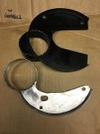
A00F0FFB-1E93-4C96-961C-585652F53D9F.jpeg
 
Currently working on fabricating an adjustable throttle pedal cover that’ll make it easier to blip the throttle for downshifting. (Tried posting a picture but got the “file too large to process” error again.)
 
Sorry I didn't get pictures yet. I routed it between the washer res and the "frame" portion. Can you not fit it there?

Looks like you did a great job.

Thanks! Some aspects of it were kind of a pita, but I’m pleased with it. Anxious to see how it works at the track Easter weekend. I’m learning as I go.

I initially had the air ducts attached where the fog lights are installed. That required a couple of (appx) 90* bends and would not clear the washer reservoir. After some helpful advice from folks here, I moved the air inlets to the outer edges of the lower grill, as shown in pics above (previous page). That location eliminates the need for the two 90* bends and fits between the frame and washer reservoir. The only downside was that I had to cut out some OEM plastic parts above & beside the area where I attached the air ducts to the grill...sometimes sacrifices have to be made for the greater good .
 
207
328
Exp. Type
HPDE
Exp. Level
3-5 Years
Scottsdale, AZ
@JDee, you asked me to keep you posted Re my brake cooling efforts...

Routing it like this clears the windshield washer reservoir. You can see that I used more flanges to connect low temp ducting to high temp (orange silicone). Doing it this way will allow me to replace the section of duct that’s subjected to rubbing/wear, without having to remove all the plastic under the car and I don’t think I’ll need to take the wheel well liner loose either:
View attachment 3630

I really like your approach with the flange to join the hoses - can you post up more on this part?
 
@gtorpedo & @JDee, I’m glad you like it; appreciate the kind words.

I started with 3” aluminum flanges I got from Aircraft Spruce. Not cheap, but good quality, in stock, and ship promptly. I’ve ordered from them multiple times and everything has been just as I expected each time.

Steps:
1) Line up the flanges with flat sides against each other.
2) Clamp them together with two sets of vice grips.
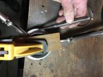
3) Clamp the pair to the workbench. I put a small piece of wood across the flange opening and then put a clamp on the wood rather than directly on the flange.
4) Use a center punch (& hammer) to make an indentation where you want to drill holes. Note: In my experience, the drill bit tends to wander off the intended spot. I noticed that happening even with a pretty obvious indent from the center punch. (I tried to make my holes as close to the middle of the half inch wide flange as I could. But, they were all off a bit and worked anyway.)
5) Drill holes. (I drilled three holes, but two or even four or five would probably work fine. I was comfortable with three. Use your best judgment.) Size the holes based on whatever you plan to use to secure the flanges. I used pop rivets. Mainly because I had them, but they might be less likely to work loose than nuts and bolts. Also, they have a little lower profile.
6) Attach the two flanges to each other with pop rivets or whatever you decide to use.

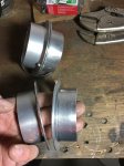
The first picture below shows four flanges. Two are finished and two are ready to start with step 1 above.

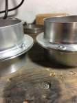
After the flanges were assembled, I used 3.25” hose clamps to connect the hose to the flanges. I tried to upload more pictures but, for some of them, I got the message that they were too big for the server to process. (I have no idea why. All pictures were taken with the same camera/phone and the resolution was the same.)
55E6C66C-B332-4F10-A13C-22C0C3D0BCA9.jpeg1DA0378F-25F2-4DA5-80D6-3FF8680D2D20.jpegFFFA245E-2659-4991-AF0F-5DC205E3D7CB.jpeg
 
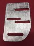
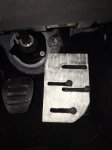
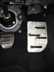
This is the pedal cover I made so I can roll my foot to the right to blip the throttle:
Gas Pedal Cover.jpg

This pic shows it installed on the gas pedal and adjustable all the way to the left (for track time):
Gas Pedal Cover Left.jpg

This pic shows the pedal cover adjusted all the way to the right: (Left edge of the cover is aligned with the left edge of the stock pedal so, spacing between brake and gas is the same as stock. The bottom right corner is curved to avoid rubbing on the carpet when the pedal cover is fully to the right.)
Gas Pedal Cover Right.jpg
 
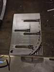
This is an unfinished version of the final pedal cover:
Unfinished final pedal cvr.jpg
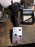
This pic shows the throttle out of the car, with my first version of the pedal cover: (It wasn't wide enough for me to easily blip the throttle.)
V1 front on pedal.jpg

This a rear view of the first version: (Roughly .5" wider than the stock pedal. The final version is about double the width of the stock pedal.)
V1 cvr rear .jpg


Notes:
1. I curved the first version to match curvature of the stock pedal. I didn't do that for the final version and it works fine.
2. I removed the pedal to make it easier to drill holes in it. But, removing the pedal is a bit of a pita. It's just hard to reach.
3. There are 3 nuts and 1 electrical connector attached to the throttle. Once I was under the dash, I used a small impact driver to remove the 3 nuts - easy. (It would take a lot longer to remove the nuts by hand.)
4. I had a hard time with the electrical connector. It has a red tab that pushes up (away from the throttle). It seemed like releasing that red tab should've allowed the connector to come apart, but it didn't. I finally got it to release by prying it off, but that seemed to leave a couple of small broken plastic bits. So, I'm guessing there's something that needs to be released in addition to the red tab. But, I just couldn't see it well enough laying on my back across the door sill with my head under the dash. So, if you remove your pedal, I suggest researching further so you don't break some part of the electrical connector.
 
Last edited:
Quick question folks...preparing to flush brake fluid with high temp stuff. I’ve flushed brake fluid many times but always guess about how much to push through the system. I do it the old fashioned way-open the line at the caliper while someone else pumps the brake pedal for me. I start with the passenger side rear; move to driver side rear; passenger side front; and finish with driver side front. I’d guess I do about 40 brake pumps for the passenger side rear; then 30; then 20; and finish at the driver front caliper with 10-15 pumps. That’s a tough guess and varies considerably if I see air bubbles or debris.

My question: assuming no bubbles or debris, how do you all determine when you’ve completely flushed out all the old fluid? (Since I’m changing it frequently, the color is the same.)
 

TMSBOSS

Spending my pension on car parts and track fees.
7,551
5,283
Exp. Type
HPDE
Exp. Level
10-20 Years
Illinois
Start by emptying the reservoir. I $3 turkey baster works best. Fill with fresh fluid and then start pumping. Expect to put a full liter through the system, at least. Hopefully there will be a slight color difference between the fluids. If you don’t have one, buy a bleeder catch bottle. It’s easier to see fluid color when it’s passing through the hose on the bottle. Good luck.
 
+1 on emptying the reservoir using a turkey baster.

My factory fill fluid was a bit over a year old and was very obviously darker than the new RBF600 I put in. I used a bit over a liter of fluid, so buy enough to do that.
 
Thanks guys! I’ve got 2 liters so that should be more than enough. It just seems like I’m always guessing how much is enough to pump through each caliper. I was hoping there might be a more precise answer. But I guess it’s all based on appearance of the fluid. I’ll be changing it in the next day or so. Heading to VIR this weekend for an HPDE.
 
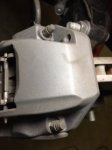
Just pulled off my wheels to flush brake fluid and realized the front calipers - 6 piston Brembo - seem to have two bleeder screws. One on the inside and another on the outside. This is my first experience with two bleeder screws. See picture:
133A7C33-0D0C-4048-8DD8-95C1E6474EF5.jpeg

I’m guessing I have to open each and bleed them separately. So, bleed each caliper twice - once from the inner screw and again from the outer.

Is that right? Does the order matter?
 

TMO Supporting Vendors

Latest posts

Buy TMO Apparel

Buy TMO Apparel
Top