The Mustang Forum for Track & Racing Enthusiasts

Taking your Mustang to an open track/HPDE event for the first time? Do you race competitively? This forum is for you! Log in to remove most ads.

  • Welcome to the Ford Mustang forum built for owners of the Mustang GT350, BOSS 302, GT500, and all other S550, S197, SN95, Fox Body and older Mustangs set up for open track days, road racing, and/or autocross. Join our forum, interact with others, share your build, and help us strengthen this community!

Let's Talk Aero

This site may earn a commission from merchant affiliate links, including eBay, Amazon, and others.

I'll have to reiterate what Olaaf said above, you need to find a wing for your goals and/or class rules. Companies that post data on their wings like we do will help you figure that out, rather then them just using the word "functional" in the title. A quick example would be if class rules limit you to a very small splitter, a huge dual element wing probably wouldn't be the best choice. Hence why when Olaaf was with our company we had a few different profiles developed by Kyle to meet a larger demand (available summer 2018). And again, full disclosure that Olaaf did own part of RHR for a little bit but has since moved on to bigger and better things. I'm pretty sure he can still chime in with some good data and CFD stuff though.
 
108
33
*Well over* It's a common industry practice to quote numbers @150mph.

That's not the Steeda wing. Not sure why you posted that abomination.

Good points. So far only hpde.
I always divided in 2 the conversation:
1. Better suspension= better slow turns.
2. Better aero= better stability in medium high speed turns.
Don't looking for max speed on the straight. (For that I'll use hp..:)

With that wing rhr did a great job improving stability at all speed. (80 miles they declared up to 200lns at only 60mph!) However 2200$ is out of budget.
It's not just stability but GRIP. There is far more time to be had increasing cornering speed and grip with downforce than what is lost from drag in a straight line.

Olaaf gave great advice. For most drivers, there is far more laptime to be had improving the driver than modifying your car. Get a data system ans make sure to find a reputable coach (you'll probably have to spend some $ on a real good one) and work on yourself.

The Steeda wing isn't aalot of money and gets rid of the rear lift with a decent amount of downforce. So if you don't want to add a splitter and want a cheap and easy solution to improve stability and improve lap times a little, it's not a bad option and then spend your money improving yourself.
 
Definitely butt dyno on the end plate comment.
 
Olaaf
Great advice. Thank you. It makes totally sense.
I ll Definetely take in consideration a pro coach.
Having this type of comparison of idea is the reason why i said thisnisbso far the bes t forum i saw.
Here we are talking about aero. So I've tried to focus questions on this. No because i want a wing tomorrow(btw in the PP1 there is a small one..) But to share knowledge and experiences. I'll probably do again for brakes , data logger and more :)
I'd like to know as much as possible.
"With the humilty to say" i wanna learn cause I'm just an amateur.

So once again thank you all
Fly

Sent from my LG-H872 using Tapatalk
 
108
33
Fwiw, the PP1 wing does not make any downforce. It actually has an upsidown Gurney flap to prevent making downforce.
 

Fair

Go Big or Go Home
Supporting Vendor
277
492
Plano, TX
I like Kyle. I have watched all his videos. ...
So key word is compromise. Not too high(will increase drag and unbalance the front) not too low(will interference with the trunk and undo the downforce)
Well... that's kind of what Kyle said, but he did say all of that with the assumption that the car in question would be fairly limited on front aero df. And with the common "tiny flat splitter + non-ducted hood" that's probably the case.

Fair3-L.jpg

But... He also said that putting the wing behind the car was advantageous for 2 reasons:

1. Leverage effect. The farther back the more torque it applies to the CG. This is a good thing when you are trying to make more rear df
2. The additive effect of the low pressure part of the wing interacting with the low pressure effect from a diffuser, when the element is behind the back of the car

And no matter how you read it, he still admitted that a high placed wing does get cleaner, more laminar flow up above the roofline. More DF and a small increase in drag up high. He just kept prefacing that it will make too much df this way, due to an assumed lack of front df.

B61G3208-L.jpg

We have done a lot of wings (using AJ's Fulcrum element) mounted 4-8" above the roofline and 0-12" behind the car. They all make a lot of rear df. And with a 6-8" front splitter and a ducted hood, maybe then add a couple of AJ's canards, its easy enough to make enough front df to not make it into an "understeering mess". :)

73990158-1029-tt_0047-L.jpg

My little BMW 330 has a 6" splitter and this high mounted rear wing and yet it is still easy to drive on faster tracks. I also like that Kyle moved AJ's team to ever larger endplates, and explained why that is advantageous. His sentiments align pretty well with what we have been doing - so I really like Kyle. ;) Even if we tend to make things in heavier materials, its seems to still be very effective.

Steeda has a twisted race wing which is also a little "out"behind the back.So it creates in theory low pressure area behind the trunk and in theory increases also the pull of the diffuser. Once again" in theory" . That is the reason why I was hoping to find some "numbers"

Look, no offense to them, but that Steeda race wing is not an optimized race wing, no matter how much people want it to be. It is mounted much too low, has much too short of a chord, and tiny end plates. Making 100 lbs of df at some unspecified speed is not that much, relative to other wings. Most of AJ's wings make 800-1000 lbs of df or more, all at usable speeds, depending on Angle of Attack.

Good points. So far only hpde.
I always divided in 2 the conversation:
1. Better suspension= better slow turns.
2. Better aero= better stability in medium high speed turns.
Don't looking for max speed on the straight. (For that I'll use hp..:)
Yea, don't worry so much about aero until you have maxed out the suspension, brakes, wheels/tires, made some power mods, and of course the #DriverMod

Here is my advice ... Don't touch your car. Hire a pro coach

Truth. We have seen the measurable results of this with some of our customers - proper coaching makes huge differences. Hard to beat this advice - but maybe get the car at least sorted and safe before you drop $5-10K on coaching. ;)

AiM-solo-L.jpg

And a data logging predictive lap timer is a cheap first step. And most coaches will require this at a minimum, at least. The $399 AiM Solo2 or $699 Solo2 DL are the industry standard. I never go on track in anything without at least my AiM Solo!! :)

Cheers,
 
Last edited:
Well... that's kind of what Kyle said, but he did day all of that with the assumption that the car were fairly limited on front aero df. And with a tiny flat splitter, non-ducted hood, that's probably the case.

Fair3-L.jpg

He also said that putting the wing behind the car was advantageous for 2 reasons:

1. Leverage effect. The farther back the more torque it applies to the CG. This is a good thing when you are trying to make more rear df
2. The additive effect of the low pressure part of the wing interacting with the low pressure effect from a diffuser, when the element is behind the back of the car

And no matter how you read it, he still admitted that a high placed wing does get cleaner, more laminar flow above the roofline. More DF and a small increase in drag. He just kept prefacing that it will make too much df this way, due to an assumed lack of front df.
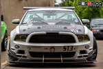
B61G3208-L.jpg

We have done a lot of wings (using AJ's Fulcrum element) mounted 4-8" above the roofline and 0-12" behind the car. They all make a lot of rear df. And with a 6-8" front splitter and a ducted hood, maybe add a couple of AJ's canards, its pretty easy to get enough front df to not make a "understeering mess". :)

73990158-1029-tt_0047-L.jpg

My little BMW 330 has a 6" splitter and this high mounted rear wing and it is easy AF to drive on faster tracks. I also like that Kyle moved to ever larger endplates and explained why that is advantageous. His sentiments align pretty well with what we have been doing - so I really like Kyle. ;)


Look, that Steeda wing is not an optimized race wing, no matter how much people want it to be. It is much too low, much too short of a chord, tiny end plates. Making 100 lbs of df at some unspecified speed is really small. Some of AJ's wings make 1000# or more.


Yea, don't worry so much about aero until you have maxed out the suspension, brakes, wheels/tires, made some power mods, and of course the #DriverMod


Truth. We have seen the results of this with some of our customers - proper coaching makes huge differences. Hard to beat this advice - but maybe get the car at least sorted and safe before you drop $5-10K on coaching.

AiM-solo-L.jpg

And a data logging predictive lap timer is a cheap first step. And most coaches will require this at a minimum, at least.

Cheers,
That's awesome.
Thanks for taking the time to answer.
As I previously said I'm here to learn. I still don't have the car yet :) so I'm using this month to dig deeper on all the info I can find on this car.

The plan is easy.
2 hpde stock. Start to " feel the car" and then , eventually, make adjustments.

I've learned more in the last week about mustang then in the previous 4 months.

Once again
Thanks for your reply.

Sent from my LG-H872 using Tapatalk
 
And no matter how you read it, he still admitted that a high placed wing does get cleaner, more laminar flow up above the roofline.

Just to clarify, the airflow isn’t laminar, it is however, attached. At our sizes and speeds, airflow is always considered turbulent. If the airflow is attached or separated is the important distinction (hence the occasional use of vortex generators that delay the separation by stealing clean air and feeding it into the attached flow).

However, the placement (up/down) of the wing is highly dependent on wing design as I’ve been learning recently. Many racing wings are heavily cambered, like the fulcrum wing, and some are not (like the brooks wing). A heavily cambered wing is GENERALLY designed to be placed in a downwash situation, since the downwash air (which may or may not be attached) hits the wing element at an angle of attack. By placing a highly cambered wing up higher you need to run more AOA to regain the “lost” natural AOA of the downwash, and you increase the moment arm applied to the chassis.

So, to have a bit of fun, I took this generic and very simple CAD model of a car below and then used Javafoil, a free airfoil design & analysis application to create a wing based on the NACA 63-2013 profile, added a couple of small tweaks, and added a gurney flap.

SimpleWings.png

The coolest thing about Javafoil (IMO) is that it can open jpg photos of airfoils. So, you can take a side on shot of your wing, splitter, or anything like that, and javafoil will open it, and let you manipulate the coordinates a bit if it needs cleaning. Remember to run the photo through perspective to orthographic projection filter in photoshop first, though. Then you can run your analysis. Plenty of tutorials out there on google. So, you can do this on your existing wing. As you’ll see in the polar plot, this wing stalls at about 8 degrees.

Since Javafoil spits out pure dimensionless coordinates, I sized this wing with a 5” chord. There are a couple of plugins to accept .DAT wing files, and I was able to use one for my CAD program (Fusion 360- check the “autodesk app store” for airfoil importer) to import the wing coordinates, and then extrude the profile into a solid and quickly slap on endplates and uprights and drop it on the car geometry. It’s about a 10% cambered wing. Some very cool airfoil tools are here: http://airfoiltools.com/plotter/index and Javafoil is a free download here: https://www.mh-aerotools.de/airfoils/javafoil.htm

Once I was done in Fusion, I exported the 3 iterations of the model and setup the openFoam cases. And then waited 60 hours as it churned through.

While I intended these runs to test my assumption that the “steeda” wing is much too close to the decklid to make any downforce, I was wrong in that assumption here. Since it’s a generic model, we don’t need to read very seriously into the values, but the wingless version made 0.2 points of lift. The low wing position version made -0.17 points of lift (downforce), and the high position wing made -0.09 of lift, and 0.02 more points of drag. Both runs were down at alpha (0) angle.

From looking at the post processing images, it seems that the extremely smooth deck lid nicely accelerates the airflow and helps it to stay well attached, assisting the suction side of the wing. I could be wrong in this assumption, as I’m a beginner in this field of aerodynamics.

So, in the real world one could install a wing on an adjustable height mount, install two manometers and put a go-pro pointed at those and get your wing height optimized..

And a data logging predictive lap timer is a cheap first step. And most coaches will require this at a minimum, at least.

Yeah, some do, some don’t even want to look at data. My coach refused to look at data until I corrected the “basics”, about halfway through the year. He even taped over my logger during test days so I couldn’t see lap times. All he needed to do was watch video or ride right seat. Data is not a panacea.. Unless you can see the issue, understand the issue, decided how you will fix the issue, and then actually do it... If Flyhalf is just starting in DE.. i'd spend the datalogger money on skidpad time and making sure the car was safe (brakes, etc.) and instruction. Enjoy the lack of chasing laptimes.

During my time in MX-5 Cup I would stare at the same (driver related) problem race after race, test after test, and the driver(s) in question couldn’t fix the problem which was inadvertently bleeding off brake pressure (not a little, a lot) during heel and toe downshifts.
 
Just to clarify, the airflow isn’t laminar, it is however, attached. At our sizes and speeds, airflow is always considered turbulent. If the airflow is attached or separated is the important distinction (hence the occasional use of vortex generators that delay the separation by stealing clean air and feeding it into the attached flow).

However, the placement (up/down) of the wing is highly dependent on wing design as I’ve been learning recently. Many racing wings are heavily cambered, like the fulcrum wing, and some are not (like the brooks wing). A heavily cambered wing is GENERALLY designed to be placed in a downwash situation, since the downwash air (which may or may not be attached) hits the wing element at an angle of attack. By placing a highly cambered wing up higher you need to run more AOA to regain the “lost” natural AOA of the downwash, and you increase the moment arm applied to the chassis.

So, to have a bit of fun, I took this generic and very simple CAD model of a car below and then used Javafoil, a free airfoil design & analysis application to create a wing based on the NACA 63-2013 profile, added a couple of small tweaks, and added a gurney flap.

SimpleWings.png

The coolest thing about Javafoil (IMO) is that it can open jpg photos of airfoils. So, you can take a side on shot of your wing, splitter, or anything like that, and javafoil will open it, and let you manipulate the coordinates a bit if it needs cleaning. Remember to run the photo through perspective to orthographic projection filter in photoshop first, though. Then you can run your analysis. Plenty of tutorials out there on google. So, you can do this on your existing wing. As you’ll see in the polar plot, this wing stalls at about 8 degrees.

Since Javafoil spits out pure dimensionless coordinates, I sized this wing with a 5” chord. There are a couple of plugins to accept .DAT wing files, and I was able to use one for my CAD program (Fusion 360- check the “autodesk app store” for airfoil importer) to import the wing coordinates, and then extrude the profile into a solid and quickly slap on endplates and uprights and drop it on the car geometry. It’s about a 10% cambered wing. Some very cool airfoil tools are here: http://airfoiltools.com/plotter/index and Javafoil is a free download here: https://www.mh-aerotools.de/airfoils/javafoil.htm

Once I was done in Fusion, I exported the 3 iterations of the model and setup the openFoam cases. And then waited 60 hours as it churned through.

While I intended these runs to test my assumption that the “steeda” wing is much too close to the decklid to make any downforce, I was wrong in that assumption here. Since it’s a generic model, we don’t need to read very seriously into the values, but the wingless version made 0.2 points of lift. The low wing position version made -0.17 points of lift (downforce), and the high position wing made -0.09 of lift, and 0.02 more points of drag. Both runs were down at alpha (0) angle.

From looking at the post processing images, it seems that the extremely smooth deck lid nicely accelerates the airflow and helps it to stay well attached, assisting the suction side of the wing. I could be wrong in this assumption, as I’m a beginner in this field of aerodynamics.

So, in the real world one could install a wing on an adjustable height mount, install two manometers and put a go-pro pointed at those and get your wing height optimized..


Yeah, some do, some don’t even want to look at data. My coach refused to look at data until I corrected the “basics”, about halfway through the year. He even taped over my logger during test days so I couldn’t see lap times. All he needed to do was watch video or ride right seat. Data is not a panacea.. Unless you can see the issue, understand the issue, decided how you will fix the issue, and then actually do it... If Flyhalf is just starting in DE.. i'd spend the datalogger money on skidpad time and making sure the car was safe (brakes, etc.) and instruction. Enjoy the lack of chasing laptimes.

During my time in MX-5 Cup I would stare at the same (driver related) problem race after race, test after test, and the driver(s) in question couldn’t fix the problem which was inadvertently bleeding off brake pressure (not a little, a lot) during heel and toe downshifts.
Thanks for the precious info olaaf.


Sent from my LG-H872 using Tapatalk
 
173
72
Would be interesting to see how OEM GT350R aero package looks with Javafoil. It’s beyond my pay grade, but if any of the high-tech guys are up for it, I’m sure there are quite a few of us who would be interested in seeing that analysis.

And thanks to all of the aero tech guys providing great info in this thread!
 
A heavily cambered wing is GENERALLY designed to be placed in a downwash situation, since the downwash air (which may or may not be attached) hits the wing element at an angle of attack. By placing a highly cambered wing up higher you need to run more AOA to regain the “lost” natural AOA of the downwash, and you increase the moment arm applied to the chassis.

Olaaf, based on tinkering do you have any rules of thumb for how close to separated flow the bottom of the wing can be and still get the benefits of "clean air?"
It would seem that keeping flow attached to the body would allow a lower wing placement, better interaction with a diffusor, and less induced drag off the wing. Does that check?
 
Would be interesting to see how OEM GT350R aero package looks with Javafoil. It’s beyond my pay grade, but if any of the high-tech guys are up for it, I’m sure there are quite a few of us who would be interested in seeing that analysis.

And thanks to all of the aero tech guys providing great info in this thread!

Just to be clear, Javafoil is a 2D analysis and design program only, so i used it to generate the airfoil used on the 3d model. You then need to use a CFD program like Fluent or openFoam (both of these are used in F1, through with their own meshers and solvers) or "lightweight/easy to use" CFD program like Autodesk CFD or the built in CFD module of Solidworks.

This is NOT a simple task of plugging in a model and letting it rip. You need to understand the finer points of meshing, boundary layers, turbulence models and mixing, there are so many variables. And you need an accurate 3D model of the car you want, then you need to simplify the model, set ride heights, and all that sort of thing. As you can see in the RHR blog posts about the S550 aero package, pitch & ride height play very important roles.
 
Olaaf, based on tinkering do you have any rules of thumb for how close to separated flow the bottom of the wing can be and still get the benefits of "clean air?"
It would seem that keeping flow attached to the body would allow a lower wing placement, better interaction with a diffusor, and less induced drag off the wing. Does that check?

Based on my tinkering, no. I'm usually surprised with what i find, the interactions of the flow structures are really complex. This is why there are professionals in this field!

Lets say you have a nice smooth rear hatch like the S550 or C6 corvette, you can imagine the the streamlines will stay nicely attached, and you can run the wing fairly low, if the wing is designed to be run in downwash. But this also changes as your vehicle dynamics changes.. Under heavy braking for example, your wing AOA is increased.. But also, the rear hatch pitches forward, and the air is able to stay attached, since it provides a shallower path to flow around. So, everything impacts everything, right?

In the example i posted above, i'm "sure" if i re-ran the CFD with the high placed with with 2-3 deg of AOA i would get back or exceed the DF of the low placed wing.. I'm also "sure" that the low placed wing would stall at 5-7 degrees, and the high placed wing would have a few more in it. I might run that simulation some point in the future, but 20 hours per run on an 8 core workstation takes up too much of my productive time that i need to spend developing my personal S197 aero package.

What you say checks with me, but it also depends on the flow structures that generate at the front of the car. In some of the RHR blog posts there are slow-mo videos of the flow structures generated by the splitter, canards, a-pillars, and wings. Take a look at those, esp. the TP slices.

One option is to look at Pro cars, like GTLM cars.. But you also need to read the rule books to understand some of their design decisions. For example they have tiny endplates on their wings.. Why? Because the ACO has a bounding box set in the rules that the wing must fit. So, don't assume that what they do is the best.. However, you can take some guiding principals.. Corvette runs their wing fairly low... Porsche runs their wing fairly high... Is that because of rear hatch slope or diffusor design?

So, i would suggest doing your own tinkering with manometers if you are really, really interested in aero, getting a phD in aerodynamics, or buy parts from companies that have done this hard work for you (hint, not steeda). I can say that the wings that RHR will offer for the S550 have all of this hard work put in by a now current F1 aero engineer, and i would use that wing at it's recommended placement and stick with it.

Or, if you are building an all out WTAC style car, hire an aerodynamics consultant like Andrew Brilliant, or Dynamic Aero Solutions. They can buy an accurate 3D model of your car, and then work in your budget and put together an aero package from a mixture of off the shelf stuff like a wing, and custom made stuff like splitters, etc. 3D printing has come along way, and it's just about getting cheap enough to get small & complex aero bits made from 3D prints, like turning vanes and canards.
 
Do we have any info on why the GT350R wing doesn't have a Gurney? I had wondered why Ford touts the wing so much while it lacks the Gurney, and just assumed it was because they didn't want to visually ruin the sleek-looking flowing lines.
 

Grant 302

basic and well known psychic
Do we have any info on why the GT350R wing doesn't have a Gurney? I had wondered why Ford touts the wing so much while it lacks the Gurney, and just assumed it was because they didn't want to visually ruin the sleek-looking flowing lines.

I'm not sure why you'd say it's lacking the gurney flap...I see it more as not needing one. It's a low production CF piece. They could have made it whatever shape they wanted.

It seems to me that with the uplift at the hood, that aero balance kept the wing with lower downforce than possible. Otherwise it would push more at high speeds than the non-R.

Gurney flaps are a great add-on when other restrictions limit the size height, mounting height, chord length, etc. of the wing. I don't think that's relevant to the R. Just my pedestrian view.
 

TMO Supporting Vendors

Buy TMO Apparel

Buy TMO Apparel
Top