- Thread starter
- #21
- Welcome to the Ford Mustang forum built for owners of the Mustang GT350, BOSS 302, GT500, and all other S550, S197, SN95, Fox Body and older Mustangs set up for open track days, road racing, and/or autocross. Join our forum, interact with others, share your build, and help us strengthen this community!
You are using an out of date browser. It may not display this or other websites correctly.
You should upgrade or use an alternative browser.
You should upgrade or use an alternative browser.
Bump Steer Adjustment Process
- Thread starter2013dibgt
- Start date
This site may earn a commission from merchant affiliate links, including eBay, Amazon, and others.
More options
Who Replied?- 6,394
- 8,275
Some random thoughts, source some longer (much longer) bolts for the subframe, support it with a jack and one by one, replace the stock bolts with the longer ones, for the most part the subframe will drop straight down making some necessary room, and it will stay lined up. It also has the added feature of just not suddenly coming loose and dropping off the car at an inopportune time. Replace the control arm bolts with the same dimensional bolt only use a hex or 12pt head and separate washer so (in theory) it will slide by the rack. Lastly, measure the toe in at normal ride height, then jack the car up about an inch and remeasure, then again in another inch. You can tape a steel ruler on the side of the frame to measure this or just measure fender height..whatever. Then do the opposite, now to lower the car you would need to either remove the springs..or uncrank the coil overs..or put the car on a lift and raise it with the frame chained to the floor, again do the measurements at both 1 and 2 inches (or whatever you did on the raised side) this way you can graph it.
The last time I did this I did it with no springs in the car so the suspension was more easily manipulated. Dragster guys normally worry about toe on the "rise" most circle track and road racers focus on the "lower" numbers.
The question is how far is the car actually moving? you can do the tired and true method of placing tire wraps on the shock housing and seeing how much they compress, or you could whip up a couple of steel pieces, a rod and a tube, affix one end to the lower a arm and one to the frame, using rod ends, and place tie wraps on those, mark the location, and see how much the tie wrap moves. This should tell you where yo need to focus and at what suspension travel to efficiently measure bump steer.
At a baseline, in real life, the control arms and tie rod ends should all be parallel with each other at normal ride height, along with things like panhard bars and misc links, so at least at NRH the suspension should not be under any bind.
- Thread starter
- #23
blacksheep-1 said:Some random thoughts, source some longer (much longer) bolts for the subframe, support it with a jack and one by one, replace the stock bolts with the longer ones, for the most part the subframe will drop straight down making some necessary room, and it will stay lined up. It also has the added feature of just not suddenly coming loose and dropping off the car at an inopportune time. Replace the control arm bolts with the same dimensional bolt only use a hex or 12pt head and separate washer so (in theory) it will slide by the rack. Lastly, measure the toe in at normal ride height, then jack the car up about an inch and remeasure, then again in another inch. You can tape a steel ruler on the side of the frame to measure this or just measure fender height..whatever. Then do the opposite, now to lower the car you would need to either remove the springs..or uncrank the coil overs..or put the car on a lift and raise it with the frame chained to the floor, again do the measurements at both 1 and 2 inches (or whatever you did on the raised side) this way you can graph it.
The last time I did this I did it with no springs in the car so the suspension was more easily manipulated. Dragster guys normally worry about toe on the "rise" most circle track and road racers focus on the "lower" numbers.
The question is how far is the car actually moving? you can do the tired and true method of placing tire wraps on the shock housing and seeing how much they compress, or you could whip up a couple of steel pieces, a rod and a tube, affix one end to the lower a arm and one to the frame, using rod ends, and place tie wraps on those, mark the location, and see how much the tie wrap moves. This should tell you where yo need to focus and at what suspension travel to efficiently measure bump steer.
At a baseline, in real life, the control arms and tie rod ends should all be parallel with each other at normal ride height, along with things like panhard bars and misc links, so at least at NRH the suspension should not be under any bind.
Thanks for the info blacksheep-1
- Thread starter
- #24
Update:
So I spent some time today taking another shot at removing the factory FLCA. After fighting with the removal of the forward FLCA bolt previously and failing miserably this time around I followed "Swiss Boss's" approach and tried cranked the steering wheel full lock in the opposite direction of the side I was working. Sweet Baby Jesus! To my amazement I found that with the wheel cranked it indeed provided enough clearance to remove the damn forward bushing bolt without having to mess with the steering rack or drop the K-member.
I owe you a few beers Swiss Boss for the time saving tip on that one..Thanks ;D
Here are a few pics of today’s progress thus far:
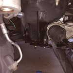
Wheel Cranked Full Lock in opposite direction. You can now kinda see the extra 1" or so of room it provided to allow the removal of the forward bushing bolt:
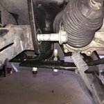
Factory FLCA removed with steering rack still in place:
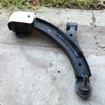
Factory FLCA on the floor defeated:


So my initial intention was to go full bore and use the Aluminium forward bushings provided in the M-5638-C kit but after realizing that I didn't really have the required press attachments to install the bushings in the arms without risking damage to the bushings or arm itself I decided to use the supplied Prothane bushings instead since they all but fell into place without much effort at all. Only time will tell if this was a mistake or not. I wasn't totally impressed with the tapered angle the Prothane bushing have on them as it looks like it may allow for arm movement/rocking while fastened to its installed location on the k-member. Hopefully this will not be the case.
Here's a shot of the Prothane bushing installed for those that care to see the orientation of it:
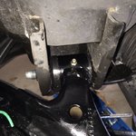
For anyone installing the hardware from the M-5638-C bushing kit here is a shot of the rearward bushing and the correct orientation for the bushing pieces included. The larger (ie..fatter) bushing closest to the FLCA itself has a concave face on one side of it. That concave face should be on the inside towards the welds which hold the shaft to the FLCA's. (Thanks Cherno134 for the info on that).
There is one other piece of info that I found out the hard way while doing the install. Hopefully mentioning this will prevent others from making the same mistake I did. When installing the reward FLCA bushing housing that FRPP provides (ie..the box framed cylinder looking contraption) there are two holes which secure this device to the K-Member by way of flag bolts. The holes on the device are of different sizes with one being quite a bit bigger than the other. Turns out that the side with the bigger hole should be installed facing inboard towards the center of the car and not the outside. Initially I didn't think it mattered how this device was oriented and didn't even notice that the inboard hole on the K-Member was also bigger then the outboard hole. I already had the damn arm installed before realizing this and almost left it alone but my OCD got the best of me and I torn it back down again to correct my mistake. I still can't make heads or tails out of why these holes are of different sizes from the factory but it is done for a reason that still escapes me. In any event, I feel better knowing they are oriented the way they were intended even if it doesn't really matter.
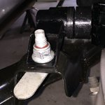
Last shot of the day of the Howe Balljoint temporarily secured in its new home:
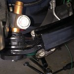
If there are no objections by the Moderators I will keep the pics and info coming as I progress further along towards the goal of adjusting the bump steer on this pig....Thanks again to all of those who provided tips during this process
So I spent some time today taking another shot at removing the factory FLCA. After fighting with the removal of the forward FLCA bolt previously and failing miserably this time around I followed "Swiss Boss's" approach and tried cranked the steering wheel full lock in the opposite direction of the side I was working. Sweet Baby Jesus! To my amazement I found that with the wheel cranked it indeed provided enough clearance to remove the damn forward bushing bolt without having to mess with the steering rack or drop the K-member.
I owe you a few beers Swiss Boss for the time saving tip on that one..Thanks ;D
Here are a few pics of today’s progress thus far:
Wheel Cranked Full Lock in opposite direction. You can now kinda see the extra 1" or so of room it provided to allow the removal of the forward bushing bolt:

Factory FLCA removed with steering rack still in place:

Factory FLCA on the floor defeated:

So my initial intention was to go full bore and use the Aluminium forward bushings provided in the M-5638-C kit but after realizing that I didn't really have the required press attachments to install the bushings in the arms without risking damage to the bushings or arm itself I decided to use the supplied Prothane bushings instead since they all but fell into place without much effort at all. Only time will tell if this was a mistake or not. I wasn't totally impressed with the tapered angle the Prothane bushing have on them as it looks like it may allow for arm movement/rocking while fastened to its installed location on the k-member. Hopefully this will not be the case.
Here's a shot of the Prothane bushing installed for those that care to see the orientation of it:

For anyone installing the hardware from the M-5638-C bushing kit here is a shot of the rearward bushing and the correct orientation for the bushing pieces included. The larger (ie..fatter) bushing closest to the FLCA itself has a concave face on one side of it. That concave face should be on the inside towards the welds which hold the shaft to the FLCA's. (Thanks Cherno134 for the info on that).
There is one other piece of info that I found out the hard way while doing the install. Hopefully mentioning this will prevent others from making the same mistake I did. When installing the reward FLCA bushing housing that FRPP provides (ie..the box framed cylinder looking contraption) there are two holes which secure this device to the K-Member by way of flag bolts. The holes on the device are of different sizes with one being quite a bit bigger than the other. Turns out that the side with the bigger hole should be installed facing inboard towards the center of the car and not the outside. Initially I didn't think it mattered how this device was oriented and didn't even notice that the inboard hole on the K-Member was also bigger then the outboard hole. I already had the damn arm installed before realizing this and almost left it alone but my OCD got the best of me and I torn it back down again to correct my mistake. I still can't make heads or tails out of why these holes are of different sizes from the factory but it is done for a reason that still escapes me. In any event, I feel better knowing they are oriented the way they were intended even if it doesn't really matter.

Last shot of the day of the Howe Balljoint temporarily secured in its new home:

If there are no objections by the Moderators I will keep the pics and info coming as I progress further along towards the goal of adjusting the bump steer on this pig....Thanks again to all of those who provided tips during this process
Great work dude. We just finished dropping and re-installing the K and steering rack on my car. Good to know this can be done with all that stuff on-car if needed.
Your factory FLCAs had some sort of heat shield on the hydro bushing! Never seen that before!
Your factory FLCAs had some sort of heat shield on the hydro bushing! Never seen that before!
- Thread starter
- #26
Yeah those heat shields are a cheap but successful fix that Ford introduced not long after I got the car new. They are "Revision C" I believe. There was a TSB that was out for quite a while for a clunking issue that many folks were experiencing in the front end. After the first two revisions failed to fix the issue someone finally figured out that it was caused by too much heat being directed at the fluid filled bushing. I had about 5K miles on the car when the FLCA's were replaced at the dealer with these shielded units.
Someone at Ford was probably feeling the heat themselves to come up with a cheap yet permanent fix for this long standing issue to avoid an embarrassing recall.
Someone at Ford was probably feeling the heat themselves to come up with a cheap yet permanent fix for this long standing issue to avoid an embarrassing recall.
- Thread starter
- #27
The marathon continues:
First off, once again I had to learn something the hard way. Initially when installing these arms I figured I would follow the diagram shown in the service manual for the proper orientation of the Flag Bolts that secure the rearward FLCA bushing mount to the K-Member. Well as it turns out, if you do this you better have a very complete set of tools at your disposal otherwise you will never get a torque wrench on the Flag Nut when it is facing up towards the sky as seen in the diagram. Its kind of funny because when I first started the disassembly of the stock FLCA's I noticed that the Service Tech at the dealer who installed my TSB replacement arms at 5K miles put the Flag bolts on "incorrectly" according to the service manual and I kind of cursed him under my breath a bit when I saw this during disassembly. Welp, I now see why it was done that way. I guess I would rather have the Flag bolts on upside down and torqued properly then have them on correctly and not be able to get at them with a torque wrench and have to wing it while trying to tighten them to 136lb ft with a 3/8 inch ratchet.
Here's a shot of the "incorrect" orientation of the Flag bolt I decided to go with:
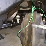
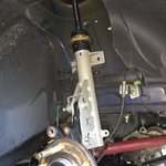
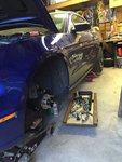
Strut removed ready for spring removal as required for the Bump Steer measurement process:

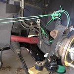
Getting creative with wire in order to keep the Spindle from flopping around like a fish with no strut attached to it:
Strut reinstalled with no Spring
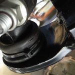
Then..I noticed this disaster! Somehow I didn't notice this nice little tear in the Balljoint boot which went unnoticed upon initial inspection when the 302S Arms first arrived. Needless to say I was pretty pissed as now I need to order new boots from Watson Racing before I can move on.
I am assuming these boots are supposed to be sealed to the Balljoint assembly in order for the grease that gets injected into the nipple at the bottom of the Arm to not ooze out all over the place. The balljoint boot itself is called a "Dust Boot" but it seems to me it would be a bad idea to ignore this slice in the rubber because as far as I can tell it also looks to help keep the grease in place. Am I mistaken on this?
Lastly, I decided that while I had everything apart it was as good a time as any to go ahead and upgrade my front struts. Currently the front Cortex struts house Koni Double Adjustable race inserts. I gave Cortex a call and placed an order for a set of JRi Double Adjustable s to replace the Konis.
If anyone is interested in low mileage (12K miles) Cortex/Koni DA 315/offset struts I will be selling a set when this project is done. They have 425 lb springs and the Ground Control Camber plates. PM me if interested.
Thats about it for now. I hope to have the new JRi replacement struts sometime next week.
First off, once again I had to learn something the hard way. Initially when installing these arms I figured I would follow the diagram shown in the service manual for the proper orientation of the Flag Bolts that secure the rearward FLCA bushing mount to the K-Member. Well as it turns out, if you do this you better have a very complete set of tools at your disposal otherwise you will never get a torque wrench on the Flag Nut when it is facing up towards the sky as seen in the diagram. Its kind of funny because when I first started the disassembly of the stock FLCA's I noticed that the Service Tech at the dealer who installed my TSB replacement arms at 5K miles put the Flag bolts on "incorrectly" according to the service manual and I kind of cursed him under my breath a bit when I saw this during disassembly. Welp, I now see why it was done that way. I guess I would rather have the Flag bolts on upside down and torqued properly then have them on correctly and not be able to get at them with a torque wrench and have to wing it while trying to tighten them to 136lb ft with a 3/8 inch ratchet.
Here's a shot of the "incorrect" orientation of the Flag bolt I decided to go with:

Strut removed ready for spring removal as required for the Bump Steer measurement process:

Getting creative with wire in order to keep the Spindle from flopping around like a fish with no strut attached to it:

Strut reinstalled with no Spring

Then..I noticed this disaster! Somehow I didn't notice this nice little tear in the Balljoint boot which went unnoticed upon initial inspection when the 302S Arms first arrived. Needless to say I was pretty pissed as now I need to order new boots from Watson Racing before I can move on.
I am assuming these boots are supposed to be sealed to the Balljoint assembly in order for the grease that gets injected into the nipple at the bottom of the Arm to not ooze out all over the place. The balljoint boot itself is called a "Dust Boot" but it seems to me it would be a bad idea to ignore this slice in the rubber because as far as I can tell it also looks to help keep the grease in place. Am I mistaken on this?

Lastly, I decided that while I had everything apart it was as good a time as any to go ahead and upgrade my front struts. Currently the front Cortex struts house Koni Double Adjustable race inserts. I gave Cortex a call and placed an order for a set of JRi Double Adjustable s to replace the Konis.
If anyone is interested in low mileage (12K miles) Cortex/Koni DA 315/offset struts I will be selling a set when this project is done. They have 425 lb springs and the Ground Control Camber plates. PM me if interested.
Thats about it for now. I hope to have the new JRi replacement struts sometime next week.
- Thread starter
- #28
Moving right along here:
I decided to move onto the driver side and start working there while I wait for the replacement Howe Boots to arrive for the passenger side. I got started by installing the 302S Bumpsteer Kit first. Based on some feedback I received from others earlier in this thread I choose to swing for the fences straight away by using the largest washer found in the kit in the top position before taking any Bump Steer measurements. My hope is that this will get me pretty close to were I need to be right out of the gate and then I can make any other changes as needed once I see the measurement results. Only time will tell if this was a good approach or not.
302S Bumpsteer Kit up close with largest washer in the stack in the top position:
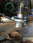
Cleaning up a little before the measurements begin:
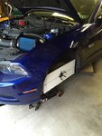
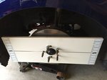
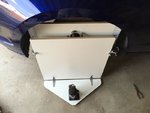
Maximum Motorsports Bump Steer Template attached to Hub:
Close up of MM Hub attachment portion of the kit:
More to come later
I decided to move onto the driver side and start working there while I wait for the replacement Howe Boots to arrive for the passenger side. I got started by installing the 302S Bumpsteer Kit first. Based on some feedback I received from others earlier in this thread I choose to swing for the fences straight away by using the largest washer found in the kit in the top position before taking any Bump Steer measurements. My hope is that this will get me pretty close to were I need to be right out of the gate and then I can make any other changes as needed once I see the measurement results. Only time will tell if this was a good approach or not.
302S Bumpsteer Kit up close with largest washer in the stack in the top position:

Cleaning up a little before the measurements begin:

Maximum Motorsports Bump Steer Template attached to Hub:

Close up of MM Hub attachment portion of the kit:

More to come later
- Thread starter
- #29
More Updates:
So I was able to do some more work on the car this past week and weekend. Before I could get too far along though I ran into a small clearance issue that had to be dealt with first. As I was preparing to do my first round of Bump measurements I decided to do a test run first. During that test I found that my FRPP Extended Wheel studs kept hitting the bump gauge towards the upper range of Bump travel. After several attempts to rearrange the Bump Gauge and having no luck I remembered that in the MM kit they included several thick spacers which were said to be used on IRS cars. I removed the gauge from the wheel hub and ended up double stacking 6 washers onto the Lug studs (2 each stud) and then reinstalled the gauge. Doing this pushed the gauge out just enough to resolve the clearance problem so I could continue.
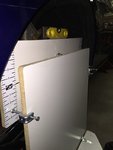
Here's a quick shot showing the gauge mounted on the wheel hub with the washers stacked behind it:
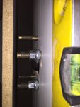
Much better:
Time to get started:
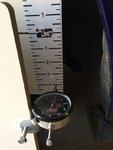
I restarted my initial round of testing now that the clearance issues were resolved. During this test I wanted to see how much suspension travel there was in the car in order to determine the range of travel to measure against. I was pretty impressed with the amount of travel these Cortex/Koni 8611 inserts allowed for. At both extremes there was 2.25" of Droop & 4" of Bump. Now if I take into consideration my cars ride height being 1.5" lower then factory in the front and then still having an additional 2.25" left in Droop I was pretty impressed to say the least. This amount of total travel in the front certainly explains why I have only once hit the bump stops up there.
Here's a shot at Full Bump just before the car was about to lift itself off the jack stands:
OK, so testing is now done lets move onto the real deal. Along the way I learned a few tricks that helped me eliminate the need to do a full round of measurements each time I fiddled with the washer stack arrangement. As documented in a previous post I first tried using just the .480 washer by itself on top but I quickly noticed some extreme swings on the Dial towards Toe-IN of the gauge as I progressed from full Droop to the first 1/2 of travel. At that point I decided to not bother documenting the values but instead just observe the gauge as I continued towards full Bump. Its a good thing I took this approach because with just the .480 washer on my car the dial kept going Toe-IN the whole time towards a full 360 sweep on the gauge. This told me right away that I wasn't even close so I knew I needed to add more spacers to the stack before documenting any values.
After seeing the amount of sweep that took place on the dial in the last test I went nuts this time and added an additional .250 washer on top of the .480 to see what would happen. Shown below is the graph from that configuration:
Ummm Yeah...looks like my ham fisted approach was a bit too much ;D

Despite the extreme swing from super Toe-IN to now an ugly Toe-OUT condition in the last round of testing I did find the results very helpful. Armed with this info I knew now that all I had to do was remove the .250 washer and use some other smaller value arrangement while also keeping the original .480 washer in place.
Next up was a .480 + .120 + .015 washer arrangement which is shown below. I knew during this test that things were looking much better because I only saw minimal movement take place on the Dial of the gauge as I cycled the suspension though its full range.
Hey now...looks like were getting somewhere:

Never being content despite the last graph looking pretty good I decided to go ahead, with fingers crossed, and remove that small .015 washer from the stack and do one last test to see where I end up. The results of the final test are shown below:
Yup...Looks good from my house. I'll take it ;D

So after 3 rounds of Bump Steer measurements completed on the Drivers side I settled on what I feel is a pretty decent compromise curve. I'll be keeping my fingers crossed that the Passenger side of the car will return duplicate measurements using the same washer stack arrangement as I used on the Drivers side but I wont be holding my breath on that one.
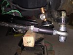
I wanted to add one more piece of info that I found out about these Boss 302S Tie Rods which I discovered along the way. It turns out these things are 5.5mm shorter then the OEM Tie Rods when measured from the end of them to the center of the spherical bearing. The 302S Tie is 96mm and the OEM Tie when measured in the same location is 101.5mm. Where this shorter distance comes into play is when you take into consideration the general consensus on how the disassembly is supposed to be done of the OEM Tie Rod in order to maintain the same Toe settings you had before you started tearing things apart. Most documentation calls for the User to loosen the locking bolt and back it off no more then a credit cards thickness away from the Toe Rod itself so you can maintain your original Toe setting when you reinstall the aftermarket Tie Rod. Thats all well and good assuming both Tie Rod units are the same length to begin with. In this case, in order to maintain the same Toe settings I needed to crank the locking nut 4.5mm closer then where it was before to make up for the difference in lengths. In my setup, before disassembly I measured the distance from the back of the locking nut to the end of the threads on the Rod itself which was 10.5mm at my original alignment settings. In the new configuration that distance is now 15mm using the 302S Bump Steer kit.
Here's a picture below for clarity purposes:
More to come later
So I was able to do some more work on the car this past week and weekend. Before I could get too far along though I ran into a small clearance issue that had to be dealt with first. As I was preparing to do my first round of Bump measurements I decided to do a test run first. During that test I found that my FRPP Extended Wheel studs kept hitting the bump gauge towards the upper range of Bump travel. After several attempts to rearrange the Bump Gauge and having no luck I remembered that in the MM kit they included several thick spacers which were said to be used on IRS cars. I removed the gauge from the wheel hub and ended up double stacking 6 washers onto the Lug studs (2 each stud) and then reinstalled the gauge. Doing this pushed the gauge out just enough to resolve the clearance problem so I could continue.
Here's a quick shot showing the gauge mounted on the wheel hub with the washers stacked behind it:

Much better:

Time to get started:

I restarted my initial round of testing now that the clearance issues were resolved. During this test I wanted to see how much suspension travel there was in the car in order to determine the range of travel to measure against. I was pretty impressed with the amount of travel these Cortex/Koni 8611 inserts allowed for. At both extremes there was 2.25" of Droop & 4" of Bump. Now if I take into consideration my cars ride height being 1.5" lower then factory in the front and then still having an additional 2.25" left in Droop I was pretty impressed to say the least. This amount of total travel in the front certainly explains why I have only once hit the bump stops up there.
Here's a shot at Full Bump just before the car was about to lift itself off the jack stands:

OK, so testing is now done lets move onto the real deal. Along the way I learned a few tricks that helped me eliminate the need to do a full round of measurements each time I fiddled with the washer stack arrangement. As documented in a previous post I first tried using just the .480 washer by itself on top but I quickly noticed some extreme swings on the Dial towards Toe-IN of the gauge as I progressed from full Droop to the first 1/2 of travel. At that point I decided to not bother documenting the values but instead just observe the gauge as I continued towards full Bump. Its a good thing I took this approach because with just the .480 washer on my car the dial kept going Toe-IN the whole time towards a full 360 sweep on the gauge. This told me right away that I wasn't even close so I knew I needed to add more spacers to the stack before documenting any values.
After seeing the amount of sweep that took place on the dial in the last test I went nuts this time and added an additional .250 washer on top of the .480 to see what would happen. Shown below is the graph from that configuration:
Ummm Yeah...looks like my ham fisted approach was a bit too much ;D

Despite the extreme swing from super Toe-IN to now an ugly Toe-OUT condition in the last round of testing I did find the results very helpful. Armed with this info I knew now that all I had to do was remove the .250 washer and use some other smaller value arrangement while also keeping the original .480 washer in place.
Next up was a .480 + .120 + .015 washer arrangement which is shown below. I knew during this test that things were looking much better because I only saw minimal movement take place on the Dial of the gauge as I cycled the suspension though its full range.
Hey now...looks like were getting somewhere:

Never being content despite the last graph looking pretty good I decided to go ahead, with fingers crossed, and remove that small .015 washer from the stack and do one last test to see where I end up. The results of the final test are shown below:
Yup...Looks good from my house. I'll take it ;D

So after 3 rounds of Bump Steer measurements completed on the Drivers side I settled on what I feel is a pretty decent compromise curve. I'll be keeping my fingers crossed that the Passenger side of the car will return duplicate measurements using the same washer stack arrangement as I used on the Drivers side but I wont be holding my breath on that one.
I wanted to add one more piece of info that I found out about these Boss 302S Tie Rods which I discovered along the way. It turns out these things are 5.5mm shorter then the OEM Tie Rods when measured from the end of them to the center of the spherical bearing. The 302S Tie is 96mm and the OEM Tie when measured in the same location is 101.5mm. Where this shorter distance comes into play is when you take into consideration the general consensus on how the disassembly is supposed to be done of the OEM Tie Rod in order to maintain the same Toe settings you had before you started tearing things apart. Most documentation calls for the User to loosen the locking bolt and back it off no more then a credit cards thickness away from the Toe Rod itself so you can maintain your original Toe setting when you reinstall the aftermarket Tie Rod. Thats all well and good assuming both Tie Rod units are the same length to begin with. In this case, in order to maintain the same Toe settings I needed to crank the locking nut 4.5mm closer then where it was before to make up for the difference in lengths. In my setup, before disassembly I measured the distance from the back of the locking nut to the end of the threads on the Rod itself which was 10.5mm at my original alignment settings. In the new configuration that distance is now 15mm using the 302S Bump Steer kit.
Here's a picture below for clarity purposes:

More to come later
BMRTech
Supporting Vendor
- 32
- 11
I just wanted to add this in here, as some people may have the same equipment (or similar pieces appropriate for the job)
This is a very last minute deal - as we are loading the car up right now to get it to the track for an event over the weekend. I only had about an hour to do this.
Basically, we made A LOT of changes to one of our cars, and the bump was insane. We added our tall ball joint A-Arms, and also took advantage of the adjustment available with them. We had a QA1 bumpsteer kit in stock, so we threw everything on and made some quick adjustments to get us by. Once the car is back, we will dial it in a little better with more accurate equipment.
Got the car up on the rack with the race plates under the front wheels.

Using some straight steel from the shop, we attach it to the wheels - so we can mount our magnetic laser level to it. This laser level has the angle adjustable line display, that we use as a base for the curve.


Traced "just" right of the laser line with a sharpie and a square

Initial settings based on what I know to commonly work well with the combination of parts we have on the car, and the method in which they are adjusted. Pretty damn good from the get go. Also keep in mind the distance from the laser, to the wall (multiplies distance) - On this base setting, we have the static ride height marked....3" of extension, and roughly 2.5" of compression

Here is a shot of (3) different tests. As you can see, various spacer configurations produce very different results.

And here are just some random shots. We installed our tall ball joint adjustable arms...and extended them out as far as possible (retained 3/4" of thread into the tube adapter/arm. This adds negative camber, adds some caster, and will slightly move the tires forward, which is what we want.


We did run into an issue with our A-Arm support brace not being wide enough, with the adjustments we wanted to run for this event. So instead of risking K-Member damage (bending the rear legs inboard) we chose to make up an adjustable piece. For these reasons, I really enjoy what I do. I may even make this a new part # and offer it. lol

In a nutshell, we made some changes late last night....and first thing this morning, we threw the car up in the air to make some changes and ensure the bump steer was not too far off. This was just a quick check....not how we adjust our cars here.
This method is great for DIYers who simply want to check and see how bad their bump in/out is.....before diving in to spending additional money on parts that they "may" not need.
This is a very last minute deal - as we are loading the car up right now to get it to the track for an event over the weekend. I only had about an hour to do this.
Basically, we made A LOT of changes to one of our cars, and the bump was insane. We added our tall ball joint A-Arms, and also took advantage of the adjustment available with them. We had a QA1 bumpsteer kit in stock, so we threw everything on and made some quick adjustments to get us by. Once the car is back, we will dial it in a little better with more accurate equipment.
Got the car up on the rack with the race plates under the front wheels.

Using some straight steel from the shop, we attach it to the wheels - so we can mount our magnetic laser level to it. This laser level has the angle adjustable line display, that we use as a base for the curve.


Traced "just" right of the laser line with a sharpie and a square

Initial settings based on what I know to commonly work well with the combination of parts we have on the car, and the method in which they are adjusted. Pretty damn good from the get go. Also keep in mind the distance from the laser, to the wall (multiplies distance) - On this base setting, we have the static ride height marked....3" of extension, and roughly 2.5" of compression

Here is a shot of (3) different tests. As you can see, various spacer configurations produce very different results.

And here are just some random shots. We installed our tall ball joint adjustable arms...and extended them out as far as possible (retained 3/4" of thread into the tube adapter/arm. This adds negative camber, adds some caster, and will slightly move the tires forward, which is what we want.


We did run into an issue with our A-Arm support brace not being wide enough, with the adjustments we wanted to run for this event. So instead of risking K-Member damage (bending the rear legs inboard) we chose to make up an adjustable piece. For these reasons, I really enjoy what I do. I may even make this a new part # and offer it. lol

In a nutshell, we made some changes late last night....and first thing this morning, we threw the car up in the air to make some changes and ensure the bump steer was not too far off. This was just a quick check....not how we adjust our cars here.
This method is great for DIYers who simply want to check and see how bad their bump in/out is.....before diving in to spending additional money on parts that they "may" not need.
Grant 302
basic and well known psychic
^I need one of those magnetic lasers too. My use of blue tape is a little too embarrassing. :-[
Is that in conjunction with moving the rear mount outward to get the wheel to move forward? I would think just moving the front out would set the wheel out and just a bit back. Increase camber, but reduce caster a little, unless the rear mount is moved too.
BMRTech said:And here are just some random shots. We installed our tall ball joint adjustable arms...and extended them out as far as possible (retained 3/4" of thread into the tube adapter/arm. This adds negative camber, adds some caster, and will slightly move the tires forward, which is what we want.
Is that in conjunction with moving the rear mount outward to get the wheel to move forward? I would think just moving the front out would set the wheel out and just a bit back. Increase camber, but reduce caster a little, unless the rear mount is moved too.
BMRTech
Supporting Vendor
- 32
- 11
The fore mount, with the bearing....extends outboard.
The rear of the arm is slotted. So you can "pull" it out. When you do this, it pivots the arm in a manner that pulls the wheels out, and a little forward - thus increasing track width, negative camber, and wheelbase slightly.
Here is a shot. Check out the rear mounts, how they are offset outboard in relation to the lower mount on the K-Member.

All this adjustment is one reason why I haven't done a BMR K member and A Arm change out.
Grant 302
basic and well known psychic
BMRTech said:The fore mount, with the bearing....extends outboard.
The rear of the arm is slotted. So you can "pull" it out. When you do this, it pivots the arm in a manner that pulls the wheels out, and a little forward - thus increasing track width, negative camber, and wheelbase slightly.
Here is a shot. Check out the rear mounts, how they are offset outboard in relation to the lower mount on the K-Member.
That's exactly what I was talking about.
Jabooh1 said:All this adjustment is one reason why I haven't done a BMR K member and A Arm change out.
Nah, that's the *best* reason to try it!
With my LS being m daily driver I worried about the length of install and adjustment time as well as my patience to get it done correctly.
Wish BMR had a satellite location in Houston.
Wish BMR had a satellite location in Houston.
BMRTech
Supporting Vendor
- 32
- 11
Jabooh1 said:All this adjustment is one reason why I haven't done a BMR K member and A Arm change out.
It is all very straight forward. Due to your concern, is why we have multiple options. The majority just bolt the standard styl K/Arms on, and take the car to an alignment shop, and done. Our stuff is built very precisely, so aligning is very easy and straight forward.
Grant 302 said:That's exactly what I was talking about.
Nah, that's the *best* reason to try it!8) My only concern is not having the Howe ball joint in there.
I agree. I love playing with various settings, etc etc.
I feel ya about the Howe Joints. However, we have had very good success with the Pro Forged units we use. We have gone through 3 suppliers, and Pro Forged has been the best thus far.
For the more racecar type, I sometimes offer to put a bearing in place of the ball joint. Those arms are sick. 3/4" Grade 12.9 bolt is the ball joint stud....so you basically have the best possible BJ height adjustments.
- Thread starter
- #37
Final Update:
Well after a bit of a set back which required me to redo the Bumpsteer settings on the car I am finally able to wrap this project up. The set back was that the alignment settings were off that I was originally using to do the previous Bump Steer measurements. Despite taking great pains to mark strut towers and Tie Rod lengths before tearing things apart it seems that the original alignment was not what I thought it was. I purchased a Caster/Camber Gauge and Toe Kit not long after my previous post here and found out that things were off enough to make a noticeable difference in my Bump Steer measurements.
After correcting the alignment on the car and redoing the Bump measurements I was able to get things back in order.
TAKE NOTE...If you decide to perform this process with your own car be sure that your alignment is what you think it is BEFORE you take the time to measure your Bump Steer. I wouldn't want others to fall into the same trap I did and waste a lot of time only to end up with measurements that are off in the end.
Anyway, I updated one of the previous pics in my last post which shows the "corrected" Tie Rod length on the car. For anyone wishing to cheat the system like I had orignaly hoped to do and just jump stright to installing the Bump Kit you may be able to get away with it if your willing to duplicate the below provided info which is based on a corner balanced configuration.
Please feel free to comment or ask any questions and I'll be glad to offer any info I can.
Thanks for following along on this project
Drivers Side FRONT:
Final ride height of 360 mm from Hub to Fender
Camber -1.6 Deg
Total Toe 0
Running a 26.7" tall wheel/tire combo (275x40x18)
Expected Drop of 1.5" from factory height
Passenger Side FRONT:
Final ride height of 367 mm from Hub to Fender
Camber -1.7 Deg
Total Toe 0
Running a 26.7" tall wheel/tire combo (275x40x18)
Expected Drop of 1.25" from factory height
Adding Rear Ride Heights for clairity purposes:
Drivers Side REAR:
Final ride height of 373 mm from Hub to Fender
Running a 26.7" tall wheel/tire combo (275x40x18)
Expected Drop of 1.75" from factory height
Passenger Side REAR:
Final ride height of 380 mm from Hub to Fender
Running a 26.7" tall wheel/tire combo (275x40x18)
Expected Drop of 1.5" from factory height
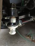
Final Bumpsteer Washer Stack Heights:
Driver Side
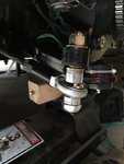
Passenger Side
Final Bumpsteer Measurements:
Driver Side
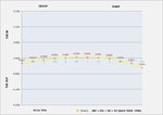
Passenger Side
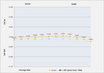
Well after a bit of a set back which required me to redo the Bumpsteer settings on the car I am finally able to wrap this project up. The set back was that the alignment settings were off that I was originally using to do the previous Bump Steer measurements. Despite taking great pains to mark strut towers and Tie Rod lengths before tearing things apart it seems that the original alignment was not what I thought it was. I purchased a Caster/Camber Gauge and Toe Kit not long after my previous post here and found out that things were off enough to make a noticeable difference in my Bump Steer measurements.
After correcting the alignment on the car and redoing the Bump measurements I was able to get things back in order.
TAKE NOTE...If you decide to perform this process with your own car be sure that your alignment is what you think it is BEFORE you take the time to measure your Bump Steer. I wouldn't want others to fall into the same trap I did and waste a lot of time only to end up with measurements that are off in the end.
Anyway, I updated one of the previous pics in my last post which shows the "corrected" Tie Rod length on the car. For anyone wishing to cheat the system like I had orignaly hoped to do and just jump stright to installing the Bump Kit you may be able to get away with it if your willing to duplicate the below provided info which is based on a corner balanced configuration.
Please feel free to comment or ask any questions and I'll be glad to offer any info I can.
Thanks for following along on this project
Drivers Side FRONT:
Final ride height of 360 mm from Hub to Fender
Camber -1.6 Deg
Total Toe 0
Running a 26.7" tall wheel/tire combo (275x40x18)
Expected Drop of 1.5" from factory height
Passenger Side FRONT:
Final ride height of 367 mm from Hub to Fender
Camber -1.7 Deg
Total Toe 0
Running a 26.7" tall wheel/tire combo (275x40x18)
Expected Drop of 1.25" from factory height
Adding Rear Ride Heights for clairity purposes:
Drivers Side REAR:
Final ride height of 373 mm from Hub to Fender
Running a 26.7" tall wheel/tire combo (275x40x18)
Expected Drop of 1.75" from factory height
Passenger Side REAR:
Final ride height of 380 mm from Hub to Fender
Running a 26.7" tall wheel/tire combo (275x40x18)
Expected Drop of 1.5" from factory height
Final Bumpsteer Washer Stack Heights:
Driver Side

Passenger Side

Final Bumpsteer Measurements:
Driver Side

Passenger Side

Similar threads
- Replies
- 4
- Views
- 2K
