The Mustang Forum for Track & Racing Enthusiasts

Taking your Mustang to an open track/HPDE event for the first time? Do you race competitively? This forum is for you! Log in to remove most ads.

  • Welcome to the Ford Mustang forum built for owners of the Mustang GT350, BOSS 302, GT500, and all other S550, S197, SN95, Fox Body and older Mustangs set up for open track days, road racing, and/or autocross. Join our forum, interact with others, share your build, and help us strengthen this community!

Correct master switch wiring..

This site may earn a commission from merchant affiliate links, including eBay, Amazon, and others.

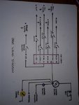
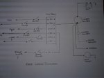
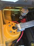
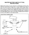
Good afternoon fellas, so I bought this master switch and im planning on tackling the job tomorrow, I just wanted to know whats the best installation route for our application. Mines a 2012 in full race trim. So the 2 main poles are pretty obvious and my concern comes down to the relay connections, first the one tagged "main electrical feed circuit" what wire exaclty do I have to run here? Then there's the ignition coil and well we dont have ONE per se.. And finally the ignition switch which cable did you guys run to here.. I appreciate you help! Happy motoring.
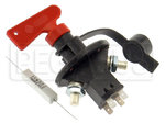
master switch.JPG

ogracing-killswitch-installation.jpg
 

captdistraction

GrumpyRacer
1,954
1,698
Phoenix, Az
on our cars the main electrical feed circuit covers the ignition, so the 2nd circuit switch (labeled 2 on either side) isn't used. The resistor is for alternator protection so you should hook that up.

That said, on S197, depending on the ruleset you're using, you can just use a large cole-hersee relay on the line between the positive battery terminal and the main fuse panel (NASA compliant). that one allows the engine to be killed, but the alternator remains connected to the battery so it can properly discharge and come to rest.

We have a nice shitshow of a thread on here somewhere, I'll go digging. What series/rules are you trying to meet?
 
6,396
8,276
The thing you are going to have to watch out for is frying the alternator when you activate the switch. in my case I ran an off/on switch to the "exciter" wire going to the alternator, this way I could use it around the pits, but turn it off on the track. The thing is, if you rotate the master. with the switch ON you fry the alternator. It looks like IMGUR has deleted a bunch of my wiring pics..

ImsXvbWl.jpg

cpkwyrTl.jpg
 
Thanks for the reply sir, im trying to make this NASA compliant, so the option you explain, correct me if im wrong is to ground the resistor and in the other side just run a "jumper wire" to the positive wire cable.. What gauge should this jumper cable be? Thanks for the replies guys!

on our cars the main electrical feed circuit covers the ignition, so the 2nd circuit switch (labeled 2 on either side) isn't used. The resistor is for alternator protection so you should hook that up.

That said, on S197, depending on the ruleset you're using, you can just use a large cole-hersee relay on the line between the positive battery terminal and the main fuse panel (NASA compliant). that one allows the engine to be killed, but the alternator remains connected to the battery so it can properly discharge and come to rest.

We have a nice shitshow of a thread on here somewhere, I'll go digging. What series/rules are you trying to meet?
 

captdistraction

GrumpyRacer
1,954
1,698
Phoenix, Az
Nasa (edit: super touring and TT - base CCR different) compliance is easier: you just need the engine to stop when you hit the kill switch. I'll bring some pictures shortly but here's an old thread (which is honestly a bit cluttered):

 
Last edited:
6,396
8,276
I really question how their switch "saves" the alternator, do they have a schematic of the internal workings of the switch? that would really help explain what's going on. One way to hedge your bet with the alternator is to determine the amperage of the alternator and wire in a (as an example) 100 amp fuse or better yet circuit breaker, in that line.
 
Well the way I see it, its not the switch itself that "saves" the alternator, when you cut off the switch you re-route the current through the relay and into the grounded resistor that slowly discharges the alternator..

I really question how their switch "saves" the alternator, do they have a schematic of the internal workings of the switch? that would really help explain what's going on. One way to hedge your bet with the alternator is to determine the amperage of the alternator and wire in a (as an example) 100 amp fuse or better yet circuit breaker, in that line.
 
531
364
sfo
I do not think we have to worry about ALT's blowing up. I would think that every modern alternator today uses TVS diode pack not only to protect the alt but all the other electrical systems subject to voltage spikes that occur for all kinds of reasons other than use racers trying to kill a running motor.


killing an S550 is the most complicated thing I have tried to do as far as killing a motor. I have tried several things without success. In the S550 case the battery is connected to a distribution box and the alt is connected to the distribution box. So you can kill the motor by severing at the distribution box and running the ALT to the battery +. When the motor is stopped this way the voltage spike got to the battery + and is absorbed and any ALT would be happy.

But while you can pass tech the distribution box still gets power around 11.5V from voltage drop through the ALT which in theory is still a hazard.

So my solution Is to simultaneously sever the power to the distribution box and the ALT with a single continuous duty 200A relay SPST. The problem is there is no ALT protection. What the voltage spike does when current flow is cut causes voltage to spike and kill ALT diodes. Diode failure is the mode of what we call alternator failure for our purposes. But from what I hear anything with modern electronics is using TVS diodes (transient voltage suppression). So in theory the ALT blowing up thing is not an issue.


I did look into the concept of cutting the field output wire, like old school ALT's with external wiring to it, but there is something internal to the S550 ALT. Cutting none of the 3 small wires coming out the ALT kills the motor when the distribution box power is cut too. I tried. So you have to get inside the ALT to cut the field output.
 
Bob, there’s another option that might work, along the wiring harness there’s white cable with blue stripe that’s the module communications network cable, it connects the ecu with the rest of the modules including the anti theft module. I discovered by accident when I simplifying my wiring harness I cutted into this cable and my car wouldn’t start and the theft light will just flash intermittently. I assume that if you tap into this cable and bridge it into the switch you can have cut the ecu signal too along with the rest of the power.
 
531
364
sfo
. I assume that if you tap into this cable and bridge it into the switch you can have cut the ecu signal too along with the rest of the power.

Very pssible. Others have done thing like cut the fuel pumps and a few other things. While they might fool a tech inspector the goal is to isolate the battery as the only power source and shut down the motor and have no other voltage anywhere except between the battery + and -.

I passed tech with my 1st cutoff and found out by accident I was still getting 11V voltage drop to the distribution box via the ALT despite severing at the + to distribution box because to make things work the ALT still needs to be connected to + and ground is still intact. That means 11V can short to ground and cause fires etc. These devices are there for our safety and I want mine to work properly. I don't even want a lonf run of 2 gauge wire from battery + to dash kill switch back to battery +. Using a continuous duty relay keeps the hot wires about 1.5Ft. That's just less to short.
 

captdistraction

GrumpyRacer
1,954
1,698
Phoenix, Az
Very pssible. Others have done thing like cut the fuel pumps and a few other things. While they might fool a tech inspector the goal is to isolate the battery as the only power source and shut down the motor and have no other voltage anywhere except between the battery + and -.

To that point, its really dependant on the rules package. For example, the rules I have to follow don't require true battery isolation; they only require the shutdown of the motor via the switch (which is a far simpler task than true full isolation of the battery and shunting the alternator properly).
 
531
364
sfo
To that point, its really dependant on the rules package. For example, the rules I have to follow don't require true battery isolation; they only require the shutdown of the motor via the switch (which is a far simpler task than true full isolation of the battery and shunting the alternator properly).

My rules are like that too. Some might say the legal minimum that kills the motor is good. Some would say the rule is ment to keep you safe so electrons stop at the battery. In my case I add about 3 feet of 2 gauge wire. Every pound counts and that weight is high above the CG. A winner is going to bend the rules as far as possible and just kill the motor with 3ft less wire. If he does that with 20 rules for the spec I guess you would call that a car prepped right to the limit. When guys come off the track how close are they to min weight? 5lbs? 50lbs? We know weight slows you down. That decision and ability to hit your target weight the closer you are the more you have invested in time and testing. F1 the guys are picking up rubber to make weight.
 
6,396
8,276
wait...the rules say you just have to kill the engine? what about the electric fuel pump?
That's insane..
This is my buddy's car at Lakeland dragstrip when the nitrous solenoid hung open, Watch the track guy run up to the back of the car and hit the kill switch.
 
531
364
sfo
That's how I approach mine, I kill the fuel pump relay, PCM ignition circuits, etc. The battery, starter/steering rack feed and alternator remain connected but all other electrical is shut down. Its certainly important to balance rules interpretation vs the safest approaches possible.

in my s550 if I leave alt connected I get an 11volt power ,from voltage drop, to the distribution box. I found that by accident. The car will not start or run but there is still shortable power with lots of current to start or maintain a fire or short. That is why I cut battery and alt cable with continuous duty relay To sever all power not between the two battery terminals. It is the safe way to do it. I have a conversation with an auto EE and he confirmed what I suspected that modern alts have TVS protection. They don’t want load dumps but know they happen enough that TVS protection is part of accepted auto electronic standards.
 

captdistraction

GrumpyRacer
1,954
1,698
Phoenix, Az
in my s550 if I leave alt connected I get an 11volt power ,from voltage drop, to the distribution box. I found that by accident. The car will not start or run but there is still shortable power with lots of current to start or maintain a fire or short. That is why I cut battery and alt cable with continuous duty relay To sever all power not between the two battery terminals. It is the safe way to do it. I have a conversation with an auto EE and he confirmed what I suspected that modern alts have TVS protection. They don’t want load dumps but know they happen enough that TVS protection is part of accepted auto electronic standards.

Thankfully, its a bit easier in S197 because the smart junction box is isolated from the battery/alternator lines (whereas in S550 they're joined at the box) so its just one easy line to interrupt and then 95% of the car no longer has any electricity to it, and the only remaining energized non-fused link is the short run to the starter motor. I don't think for S550 you could do it much differently than you did. Good to know on TVS protection, separate conversation I need to have someday is to find out why our alternators tend to randomly die with heavy track use (RPMs?)
 

TMO Supporting Vendors

Buy TMO Apparel

Buy TMO Apparel
Top