The Mustang Forum for Track & Racing Enthusiasts

Taking your Mustang to an open track/HPDE event for the first time? Do you race competitively? This forum is for you! Log in to remove most ads.

  • Welcome to the Ford Mustang forum built for owners of the Mustang GT350, BOSS 302, GT500, and all other S550, S197, SN95, Fox Body and older Mustangs set up for open track days, road racing, and/or autocross. Join our forum, interact with others, share your build, and help us strengthen this community!

Dedicated Track conversion

This site may earn a commission from merchant affiliate links, including eBay, Amazon, and others.

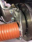
Can someone explain to me the advantage of using a full backing plate on the brakes for cooling?

Here is a picture of the Vorschlag 2018 GT project car with a full plate
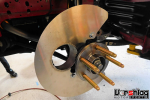
upload_2018-6-5_17-30-3.png

I did see a picture that Spartan posted of the GT4 hose hub adapter, the carbon fiber piece and it did not integrate into a full backing plate. I know that they had problems with cooling and I am sure that they did their homework on the final design. I would think that if Ford engineers didn't use a full backing plate there must not be any advantage to using one.

Here is another picture of the Vorsclag setup on their 2018 GT with 4" hose. If I did this on the GT350 the tire would rub on the hose with anymore then 1/2 turn of the wheel :) Maybe the car is only driven in a straight line :)

upload_2018-6-5_17-34-1.png

picture credits go to Vorschlag
 
Last edited:
Can someone explain to me the advantage of using a full backing plate on the brakes for cooling?

Here is a picture of the Vorschlag 2018 GT project car with a full plate

View attachment 4286

I did see a picture that Spartan posted of the GT4 hose hub adapter, the carbon fiber piece and it did not integrate into a full backing plate. I know that they had problems with cooling and I am sure that they did their homework on the final design. I would think that if Ford engineers didn't use a full backing plate there must not be any advantage to using one.

Here is another picture of the Vorsclag setup on their 2018 GT with 4" hose. If I did this on the GT350 the tire would rub on the hose with anymore then 1/2 turn of the wheel :) Maybe the car is only driven in a straight line :)

View attachment 4287

picture credits go to Vorschlag

The more of the ID of the rotor that is ducted the better the air is able to enter into the rotors veins and help cool the rotor.

Simply having a flat plate on the inner rotor surface does nothing if only cooling the friction surface of just one side of the rotor. Not very efficient at all.


Sent from my iPhone using Tapatalk
 
757
1,118
TX
This discussion has been great so far. These photos are exceptionally hard to find on he interwebz unless I am ultra-challenged at searching.

Has anyone read any data on the effectiveness of something like Vorshlag plates that just dump the air into the inside of one side of the rotor vs. something more like what Spartan posted (which has cavities to direct airflow around the entire wheel hub)?

Wondering what the improvement deltas of something like @blk2017's setup vs. a full-on race solution like on the GT4s is over OEM.
 
757
1,118
TX
The 3D printed brake cooling part is made for the Brembo stock setup. Won’t work for those using the AP setup.


Sent from my iPhone using Tapatalk

By chance have you heard anymore about these being available to others? Very interested in a set...
 
4b4f800c7a1442940bb0fc47e873488c.jpg
This is the duct from the FP350S. it’s not very effective or efficient because It doesn’t direct air directly into the rotors ID.

4948cecb4b69b508c044538ed86f392d.jpg
This is from the GT4. Notice how it encloses the rotor ID and forces air into the rotors veins to help cool the rotor and wheel bearing.


Sent from my iPhone using Tapatalk
 
This discussion has been great so far. These photos are exceptionally hard to find on he interwebz unless I am ultra-challenged at searching.

Has anyone read any data on the effectiveness of something like Vorshlag plates that just dump the air into the inside of one side of the rotor vs. something more like what Spartan posted (which has cavities to direct airflow around the entire wheel hub)?

Wondering what the improvement deltas of something like @blk2017's setup vs. a full-on race solution like on the GT4s is over OEM.

If you’re going to go to the trouble of doing brake ducts may as well do it right and take full advantage of the benefits. Cooling just the inner friction surface of the rotor doesn’t cool the rotors outer surface or provide efficient thermal cooling.


Sent from my iPhone using Tapatalk
 
757
1,118
TX
If you’re going to go to the trouble of doing brake ducts may as well do it right and take full advantage of the benefits. Cooling just the inner friction surface of the rotor doesn’t cool the rotors outer surface or provide efficient thermal cooling.


Sent from my iPhone using Tapatalk

Fully agree. Just wondering where I can I source a duct for the rotor or work with someone to produce. If not readily available, would just like to know the data points on how much I am leaving on the table.
 
492
387
DFW, TX
If you’re going to go to the trouble of doing brake ducts may as well do it right and take full advantage of the benefits. Cooling just the inner friction surface of the rotor doesn’t cool the rotors outer surface or provide efficient thermal cooling.


Sent from my iPhone using Tapatalk
Cooling the inner face is a recipe for cracked rotors. Seen it many times. Has to be directed to the eye as best as possible.

Sent from my SAMSUNG-SM-G900A using Tapatalk
 
757
1,118
TX
Cooling the inner face is a recipe for cracked rotors. Seen it many times. Has to be directed to the eye as best as possible.

Sent from my SAMSUNG-SM-G900A using Tapatalk

I assume this is because you're directing the majority of air onto one side of the rotor vs. primarily through the veins where it cools both faces?
 
492
387
DFW, TX
I assume this is because you're directing the majority of air onto one side of the rotor vs. primarily through the veins where it cools both faces?
Yes. If you cool one side and not the other you'll get one side with cracks.

These aren't cracks from too much heat that you will see normally, they will crack across the entire face on the cool side especially on straight vane rotors.

Sent from my SAMSUNG-SM-G900A using Tapatalk
 
It's surprising nobody has developed a good solution for this to date. The first GT350's hit the street almost three years ago. That CF piece looks nice. If Multimatic made it I'm sure it's very expensive but functional.
 
Capaldi is going to use my car to design an AP racing cooling set up. I told them we may have up to a half a dozen people that would be interested in purchasing this product from them.


Sent from my iPhone using Tapatalk

I’m in for ducts if Capaldi makes them for our AP brake set up.
I know of at least 3 other guys besides us that may also be of interest.


Sent from my iPhone using Tapatalk
 
I agree with VoodooBoss that the backing plate from Kohr or Multimatic will cost dearly. Even the 3D printed piece from Capaldi Racing will cost a lot to tool up and fabricate from carbon fiber.

I’m an engineer even though not a mechanical engineer and challenges like this won’t let me rest until I find a solution. Woke up this morning with an idea which I believe is cheap and easy to fabricate and effective. Would love to hear what you guys think. I think its so simple that even I could make this :)

Thanks to spartan, 8250RPM, bpracer, and Black Boss for ideas, theory, pictures! This input gets the gears turning.

Brake cooling is a problem on the GT350. I overheated the stock pads first time out which caused deposits on the rotors. No fade or fluid problems. Rims were so hot I burned my fingers getting the stock metal tire valves off to let air out between sessions. Brake cooling is a must and will help keep the hub bearing from eventually failing.

I apologize for the crude drawing but I don’t have any software for something like this and I don’t have the car next to me for actual dimensions but I think it conveys the idea.

upload_2018-6-7_9-3-23.png


Basically it’s a backing plate of aluminum (green piece) that needs to be fairly stiff so it won’t flex when the hose tugs on it. Open for ideas of how thick it needs to be. Its mounted at the 3 mounting points for the factory backing plate. 3rd hole (upper hole) needs to be drilled and taped but its there.

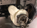
Now the plate needs to be mounted closer to the rotor as the normal backing plate mounting lugs provide. I think that an aluminum stand off dowel (1” dia) with a hole through the center would work. Could even drill and tap the factory holes for a slightly larger bolt. Need to bring the plate out to the same plane as the white 3D printed piece does. Basically just forward of where the hub mounts to the carrier. This will allow the plate to seal around the hub. A tight fit here will keep the air at the hub. Should also cool the bearing in the hub better. Tighter the seal here the less air can escape.

The plate needs to be on the same plane as seen here.

upload_2018-6-7_9-6-3.png

You also see how much further back the mounting bolts are thus the aluminum spacers to bring the plate forward to the same plane.

Obviously, you will need to remove the hub to get this in place.

The OD of the backing plate is slightly larger (5mm?) then the ID of the center of the rotor. No need to cover the inside friction surface of the rotor.

The red piece in the drawing, I’ll call it a fence, is nothing more then a thin L shaped piece of aluminum. It needs relief cuts on the mounting surface so that it can be bent into a circle. Only need pop rivets to attach it to the plate. The diameter needs to be 1-2mm? less then the ID of the rotor opening. The height of the "fence" needs to be such that it doesn't block the rotor vein openings.

To get this precise, you could mount the backing plate on a piece of plywood with a screw at the center (before you cut out the hub opening) and screw a block of wood at the desired diameter of the fence to the plywood and turn and mount the fence piece by piece to keep the gap to the rotor precise and perfectly round.

I believe that this should seal off the back of the rotor fairly well.

This should be easy to do for whatever rotor diameter you are using, Brembo or AP Racing.

Only issue is getting the hose to the backing plate. Impressive what 8250RPM did with forming the aluminum pipe from 4” down to an oval.

I am just wondering if you could make something out of wood or Styrofoam and then use body filler (like when they make speaker boxes) to make a mold and then wrap the mold with either carbon fiber or fiberglass.

Since the plate is so simple this might be easy to do the whole thing in carbon fiber???

I think this is what makes America (and American's) Great. Its our ingenuity and drive to find solutions!

Thoughts? Other ideas? Improvements? Effectiveness? Easy to fabricate?
 
Last edited:
My misfire codes caused rich fuel and destroyed my cats.
3aef93f02dcce2c07745d57219d4f3fe.jpgd9a0fc879a555457d710248c36fb37b5.jpg

Installed catless downpipes and the engine runs great. A ford engineer with a computer turned off the crank position sensor because it no longer works on a CP 5.2. He will tune it soon.


Sent from my iPhone using Tapatalk
 
I agree with VoodooBoss that the backing plate from Kohr or Multimatic will cost dearly. Even the 3D printed piece from Capaldi Racing will cost a lot to tool up and fabricate from carbon fiber.

I’m an engineer even though not a mechanical engineer and challenges like this won’t let me rest until I find a solution. Woke up this morning with an idea which I believe is cheap and easy to fabricate and effective. Would love to hear what you guys think. I think its so simple that even I could make this :)

Thanks to spartan, 8250RPM, bpracer, and Black Boss for ideas, theory, pictures! This input gets the gears turning.

Brake cooling is a problem on the GT350. I overheated the stock pads first time out which caused deposits on the rotors. No fade or fluid problems. Rims were so hot I burned my fingers getting the stock metal tire valves off to let air out between sessions. Brake cooling is a must and will help keep the hub bearing from eventually failing.

I apologize for the crude drawing but I don’t have any software for something like this and I don’t have the car next to me for actual dimensions but I think it conveys the idea.

View attachment 4317


Basically it’s a backing plate of aluminum (green piece) that needs to be fairly stiff so it won’t flex when the hose tugs on it. Open for ideas of how thick it needs to be. Its mounted at the 3 mounting points for the factory backing plate. 3rd hole (upper hole) needs to be drilled and taped but its there.

Now the plate needs to be mounted closer to the rotor as the normal backing plate mounting lugs provide. I think that an aluminum stand off dowel (1” dia) with a hole through the center would work. Could even drill and tap the factory holes for a slightly larger bolt. Need to bring the plate out to the same plane as the white 3D printed piece does. Basically just forward of where the hub mounts to the carrier. This will allow the plate to seal around the hub. A tight fit here will keep the air at the hub. Should also cool the bearing in the hub better. Tighter the seal here the less air can escape.

The plate needs to be on the same plane as seen here.

View attachment 4318

You also see how much further back the mounting bolts are thus the aluminum spacers to bring the plate forward to the same plane.

Obviously, you will need to remove the hub to get this in place.

The OD of the backing plate is slightly larger (5mm?) then the ID of the center of the rotor. No need to cover the inside friction surface of the rotor.

The red piece in the drawing, I’ll call it a fence, is nothing more then a thin L shaped piece of aluminum. It needs relief cuts on the mounting surface so that it can be bent into a circle. Only need pop rivets to attach it to the plate. The diameter needs to be 1-2mm? less then the ID of the rotor opening. The height of the "fence" needs to be such that it doesn't block the rotor vein openings.

To get this precise, you could mount the backing plate on a piece of plywood with a screw at the center (before you cut out the hub opening) and screw a block of wood at the desired diameter of the fence to the plywood and turn and mount the fence piece by piece to keep the gap to the rotor precise and perfectly round.

I believe that this should seal off the back of the rotor fairly well.

This should be easy to do for whatever rotor diameter you are using, Brembo or AP Racing.

Only issue is getting the hose to the backing plate. Impressive what 8250RPM did with forming the aluminum pipe from 4” down to an oval.

I am just wondering if you could make something out of wood or Styrofoam and then use body filler (like when they make speaker boxes) to make a mold and then wrap the mold with either carbon fiber or fiberglass.

Since the plate is so simple this might be easy to do the whole thing in carbon fiber???

I think this is what makes America (and American's) Great. Its our ingenuity and drive to find solutions!

Thoughts? Other ideas? Improvements? Effectiveness? Easy to fabricate?

I’m a mechanical engineer myself. I design in 3D solidworks. I think the plate design could be modeled up and 3D printed actually. There are companies doing phenomenal things with 3D printed parts these days. Even metal printing. There is a company doing fairly inexpensive 3D printers that use fiberglass or Kevlar filament interspersed within the base material used. I would choose a nylon 6/6 as the base material. I looked at these printers for my company when we were going to print connectors for our machine in house vs getting them machined. Cost of like 10-12 bucks in material vs 500 in machining. The job doing this went outside to the owners son business instead. He is printing us production parts now. I would need to get some measurements and draw up the key suspension areas that we would interface with. Hmmm.


Sent from my iPhone using Tapatalk
 

TMO Supporting Vendors

Buy TMO Apparel

Buy TMO Apparel
Top