- 6,394
- 8,275
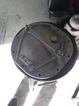
OK, so back from the races, as you will recall, I had an 8.8 diff with a little "wang " in it. There are several issues here, one is how to measure the wang, and 2 which side is the wang on.. so here we go.
So to determine the amount of wang, we need to create a jig whereby the angle of wang can be measured.
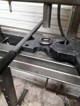
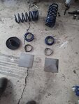
Looking around the shop, I scrounged up some plates used to support a roll cage, I cut a 31/4 inch hole in them
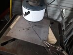
I then halve them
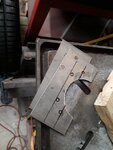
hold them up to the axle flange and mark the holes, I do this front to back as well as up and down because the holes are different lengths. Also, it's not so important to get the holes perfect since the whole idea is to get the plate to index on the axle flange, and miss the axle tube, so.. the holes are marked, then drilled out with a 3/8 drill, leaving plenty of wobble room for the 5/16 bolts and nuts. There is a reason the flange is cut in half, so I can use them with the axle in the car.
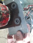
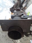
I then locate some 1/2 inch square tube, cut to length, I clamp the square tubing to the flange in a vice so they won't move and weld them together
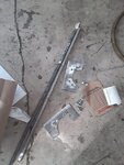
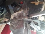
I can now measure the angle of wang
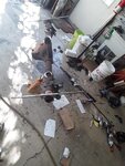
But.. WHICH side is the wang on, and how do we know what is center?
and how do we determine the DBO point of reference?
Well, for the back of the unit, we measure the width of the upper TRAILING arm bracket and divide by half, I then drill an index point in the housing.
(DBO= dead balls on)
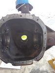
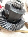
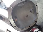
I then run a string down that reference point to the ground, checking to make sure it's 90 degrees, and mark the diff housing, you can also reference the bolt holes for the cover, they should be the same distance to center, the ring gear offset is plainly visible.
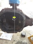
I then run the string through the pinion hole, out the bottom and mark that point, from my cover DBO center reference.
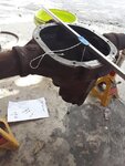
I reference that point and mark the housing, then I cross reference the string mark with a measurement from the "pig" or center section, flanges where they meet the axle tubes. This will establish the DBO for the pinion side of the unit.
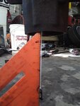
I clamp this with a furniture clamp and now I have a Golden DBO referenced center of the diff
(GDBO= really , really DBO)
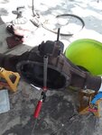
I can now measure from my GDBO reference to the flange jigs and tell which side has the wang in it, in this case it was the right.
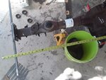
Barring being able to cram this into some kind of press, or someone you know actually owning a diff press
how do we adjust this? you say..
I thought you'd never ask
Enter the maximum force adjustment tool.
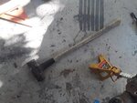
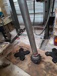
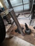
I place the unit on jack stands, off set so that the bent side (the side I wanted narrower) would face up, and that side was supported at the end of the tube, and on the other, the opposite side of the pig, so according to the Geneva convention, when you strike the pig on it's flange, the unsupported (right in this case) side must bend straighter.. after awhile, and honestly after a few misses as well, it did move, was able to get within our spec of 1/8 inch and then that sucker refused to move again.. but I had one more card to play.
I cranked the welder up to nuclear, welded the section that I wanted narrower and quenched it with a rag dipped in water, and it took another 1/16 inch out of it.
So the unit was within 1/16th of straight, totally in "close enough" range. (We started with a 1/4 plus toe out)
I then welded the tubes in (not quenching them), and I'll tell you right here and now, I apologize for the welds, apparently I forgot how to weld after a few months, ground off the crudeness (or most of it anyway) and primed it with metal etching primer.
I then rechecked for camber and toe, and camber was 1/8 toe (out) was 1/16th.
Done, my back is screaming at me...
I don't think I left anything out.
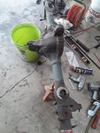
So to determine the amount of wang, we need to create a jig whereby the angle of wang can be measured.
Looking around the shop, I scrounged up some plates used to support a roll cage, I cut a 31/4 inch hole in them

I then halve them

hold them up to the axle flange and mark the holes, I do this front to back as well as up and down because the holes are different lengths. Also, it's not so important to get the holes perfect since the whole idea is to get the plate to index on the axle flange, and miss the axle tube, so.. the holes are marked, then drilled out with a 3/8 drill, leaving plenty of wobble room for the 5/16 bolts and nuts. There is a reason the flange is cut in half, so I can use them with the axle in the car.


I then locate some 1/2 inch square tube, cut to length, I clamp the square tubing to the flange in a vice so they won't move and weld them together


I can now measure the angle of wang

But.. WHICH side is the wang on, and how do we know what is center?
and how do we determine the DBO point of reference?
Well, for the back of the unit, we measure the width of the upper TRAILING arm bracket and divide by half, I then drill an index point in the housing.
(DBO= dead balls on)

I then run a string down that reference point to the ground, checking to make sure it's 90 degrees, and mark the diff housing, you can also reference the bolt holes for the cover, they should be the same distance to center, the ring gear offset is plainly visible.

I then run the string through the pinion hole, out the bottom and mark that point, from my cover DBO center reference.

I reference that point and mark the housing, then I cross reference the string mark with a measurement from the "pig" or center section, flanges where they meet the axle tubes. This will establish the DBO for the pinion side of the unit.

I clamp this with a furniture clamp and now I have a Golden DBO referenced center of the diff
(GDBO= really , really DBO)

I can now measure from my GDBO reference to the flange jigs and tell which side has the wang in it, in this case it was the right.

Barring being able to cram this into some kind of press, or someone you know actually owning a diff press
how do we adjust this? you say..
I thought you'd never ask
Enter the maximum force adjustment tool.

I place the unit on jack stands, off set so that the bent side (the side I wanted narrower) would face up, and that side was supported at the end of the tube, and on the other, the opposite side of the pig, so according to the Geneva convention, when you strike the pig on it's flange, the unsupported (right in this case) side must bend straighter.. after awhile, and honestly after a few misses as well, it did move, was able to get within our spec of 1/8 inch and then that sucker refused to move again.. but I had one more card to play.
I cranked the welder up to nuclear, welded the section that I wanted narrower and quenched it with a rag dipped in water, and it took another 1/16 inch out of it.
So the unit was within 1/16th of straight, totally in "close enough" range. (We started with a 1/4 plus toe out)
I then welded the tubes in (not quenching them), and I'll tell you right here and now, I apologize for the welds, apparently I forgot how to weld after a few months, ground off the crudeness (or most of it anyway) and primed it with metal etching primer.
I then rechecked for camber and toe, and camber was 1/8 toe (out) was 1/16th.
Done, my back is screaming at me...
I don't think I left anything out.

Last edited:
