This is the Build Thread for Stangra DIB GT. Reply below.
- Welcome to the Ford Mustang forum built for owners of the Mustang GT350, BOSS 302, GT500, and all other S550, S197, SN95, Fox Body and older Mustangs set up for open track days, road racing, and/or autocross. Join our forum, interact with others, share your build, and help us strengthen this community!
You are using an out of date browser. It may not display this or other websites correctly.
You should upgrade or use an alternative browser.
You should upgrade or use an alternative browser.
S197 Stangra DIB GT Build Thread Profile - S197 Mustangs
- Thread starterStangra
- Start date
This site may earn a commission from merchant affiliate links, including eBay, Amazon, and others.
More options
Who Replied?Bill Pemberton
0ld Ford Automotive Racing Terror
Loved your last comment on your build asking how in the heck all these mods happened , but I do concur you definitely need to get to the track to check out the potential!! Nice build, great color, and welcome to the Pistonhead World of Mad Modders!
- Thread starter
- #3
Thanks, I guess I should've said I gotta get to the track more!
I joined NASA Northern CA last year but so far:
1st HPDE event I registered for it rained heavily and I wanted at least my initiation to be dry, rescheduled.
Actual first event was Thunderhill, Had a great time!...still overall a humbling experience though.
Second event at Sonoma, much improved. Realizing how much more there is to learn, also how addictive this is gonna be!
Time conflicts kept me away a few months but registered for my 3rd event at Sonoma last October only to have event cancelled due to the huge fires.
Ready to go & currently registered for 2 days at Sonoma May 8th & 9th but in light of all the recent events these dates are doubtful too.
I will get out there again ASAP!
Bill Pemberton
0ld Ford Automotive Racing Terror
Both an SCCA and NASA member and both are good sources for automotive events. Hear nothing but good things about the NorCal NASA Region and you have been able to run on two tracks on many folks bucket lists. With Buttonwillow and Laguna Seca to the South, you will have some great stories to share on the TMO Forum in the future and glad to see you have had a chance to track you Blue Beast!!
Since your intercooler is without fans, how have your temps been?
- Thread starter
- #6
I'm a believer in the fans-impede-airflow at track speed theory. I haven't driven a lot of events but have yet to see problems with my IAT's. While not an intercooler issue, at Thunderhill with 104° ambient, eng temp was a problem & I threw a P1299 code (cyl. head overtemp). Last September I added better hood vents and E85 to hopefully alleviate this a bit but haven't got a track day since. Still trying to find an effective fit for an oil cooler, tricky with all the space occupied by the intercooler HE & A/C condenserSince your intercooler is without fans, how have your temps been?
- Thread starter
- #7
Back in the saddle and off to the Track soon!!!
So, it’s been 1-1/2 years since my last track event...
It feels like an era of my life has elapsed while accomplishing a myriad of upgrades. What started out as just a few heat abatement items somehow had expanded! As my scope of work grew; devising, sourcing and/or fabricating solutions to get everything to fit and play well together on a dual-purpose street/track car while waiting on parts from vendors during COVID has finally brought me here. If you're still following, be patient, it may take a while for me to sort through all my pics and get 'em posted in an understandable sequence. I'll start with this:
During track sessions in 2020 I realized that I needed some better cooling solutions for my supercharged engine and knew an oil cooler purchase should be high on the list. I was leaning towards a Setrab unit, but I also needed a significant upgrade to my intercooler system as well. This seemed like the time to do both. Now, keeping the A/C condenser too while finding the real estate for all this is a bit of a challenge so I ultimately settled on a Mishimoto oil cooler that’s thin enough to squeeze into a 4 heat exchanger stack. Still hoping this wasn't a mistake. Also, high IATs and heat soak have been a problem when commanding repeated WOT on the track. My ¾" Intercooler system plumbing wasn’t keeping up so I’ve upsized every component in the system for increased capacity and coolant flow. I ordered and waited a looong time for a Department of Boost Titanic Heat Exchanger, and after unboxing it took about 2 min. to realize it would require some convincing to make it fit into my ‘14 GT. Aptly named, this thing is big enough to interfere with the upper grille fog lights & my existing Vorshlag Brake Cooling Inlets, the 20AN ORB outlet conflicted with the Upper Bumper Cover Support, and the Radiator Support Frame would need to be trimmed some too to accommodate 1-¼" plumbing.
So, it began...
Previous Intercooler H/E with 3/4" outlet:
New intercooler is BIGGER

The Upper Bumper Support Bracket has bulky legs that attach to another plastic fitting on the Radiator Support Frame, My solution:


Fortunately there's a conveniently located flat area suitable for modification.


![20210417_151456[1].jpg](https://trackmustangsonline.com/data/attachments/73/73152-fbacc36c83678fa786b94a409c857a4a.jpg "20210417_151456[1].jpg")

I was able to find just enough room for both the Heat Exchanger and an Oil Cooler. I started by re-making the H/E mount brackets that Dept. of Boost provides with the unit to allow a slightly more forward location. While I was at it I added provisions for rubber vibration isolating mount bushings.

I found a Mishimoto Oil Cooler with a thin enough profile that I could fit it between the Radiator and A/C Condenser. This required moving the condenser forward by adding spacers and longer bolts to the existing attach points. The Oil Cooler is supported by a support frame mounted to the Radiator lower flange and using locations intended for an automatic transmission cooler.
.jpg")
.jpg")
A 4 heat exchanger stack:
.jpg")
All of this was fabricated with provisions for boxing in the airflow through everything at final installation... and that's a story for next post. I'll just say this; ducting everything while retaining the A/C condenser, the stock crash bar bumper, and hood latch configuration was a nearly overwhelming job for me. I don't know how many hours (weeks !) I spend working all that out but If I ever had to do it again, all these would have to go!
The Intercooler H/E was a bit wider than my previous unit and my Vorshlag Brake Duct Inlets had to go, I made these with an offset angle and had to relocate a bit to clear it.


So, it’s been 1-1/2 years since my last track event...
It feels like an era of my life has elapsed while accomplishing a myriad of upgrades. What started out as just a few heat abatement items somehow had expanded! As my scope of work grew; devising, sourcing and/or fabricating solutions to get everything to fit and play well together on a dual-purpose street/track car while waiting on parts from vendors during COVID has finally brought me here. If you're still following, be patient, it may take a while for me to sort through all my pics and get 'em posted in an understandable sequence. I'll start with this:
During track sessions in 2020 I realized that I needed some better cooling solutions for my supercharged engine and knew an oil cooler purchase should be high on the list. I was leaning towards a Setrab unit, but I also needed a significant upgrade to my intercooler system as well. This seemed like the time to do both. Now, keeping the A/C condenser too while finding the real estate for all this is a bit of a challenge so I ultimately settled on a Mishimoto oil cooler that’s thin enough to squeeze into a 4 heat exchanger stack. Still hoping this wasn't a mistake. Also, high IATs and heat soak have been a problem when commanding repeated WOT on the track. My ¾" Intercooler system plumbing wasn’t keeping up so I’ve upsized every component in the system for increased capacity and coolant flow. I ordered and waited a looong time for a Department of Boost Titanic Heat Exchanger, and after unboxing it took about 2 min. to realize it would require some convincing to make it fit into my ‘14 GT. Aptly named, this thing is big enough to interfere with the upper grille fog lights & my existing Vorshlag Brake Cooling Inlets, the 20AN ORB outlet conflicted with the Upper Bumper Cover Support, and the Radiator Support Frame would need to be trimmed some too to accommodate 1-¼" plumbing.
So, it began...
Previous Intercooler H/E with 3/4" outlet:
New intercooler is BIGGER
The Upper Bumper Support Bracket has bulky legs that attach to another plastic fitting on the Radiator Support Frame, My solution:
Fortunately there's a conveniently located flat area suitable for modification.
I was able to find just enough room for both the Heat Exchanger and an Oil Cooler. I started by re-making the H/E mount brackets that Dept. of Boost provides with the unit to allow a slightly more forward location. While I was at it I added provisions for rubber vibration isolating mount bushings.
I found a Mishimoto Oil Cooler with a thin enough profile that I could fit it between the Radiator and A/C Condenser. This required moving the condenser forward by adding spacers and longer bolts to the existing attach points. The Oil Cooler is supported by a support frame mounted to the Radiator lower flange and using locations intended for an automatic transmission cooler.
A 4 heat exchanger stack:
All of this was fabricated with provisions for boxing in the airflow through everything at final installation... and that's a story for next post. I'll just say this; ducting everything while retaining the A/C condenser, the stock crash bar bumper, and hood latch configuration was a nearly overwhelming job for me. I don't know how many hours (weeks !) I spend working all that out but If I ever had to do it again, all these would have to go!
The Intercooler H/E was a bit wider than my previous unit and my Vorshlag Brake Duct Inlets had to go, I made these with an offset angle and had to relocate a bit to clear it.
Last edited:
Did you fab all those brackets your self??? If so way to go those brake ducts they look great! Like the loook of the welds on the 45s nice work
- Thread starter
- #9
Thank you for those kind words. I fabricated all my parts for this project but had a friend do my welding for me. I'll share your comments with him.
- Thread starter
- #10
I got to thinking about everything else that I wanted to do up front since I had the bumper cover off anyway... soon a classic case of project creep set in. Probably shoulda started with a gauge install for the credit card!
I had a lot of time consuming stuff to do first though.
Fencing the airflow through the radiator has been on my mind since I first supercharged the car, but it seemed a bit daunting with the whole supercharger mod at the time and it didn't seem like an easy thing to tackle with the A/C condenser in place. It's not. Now, since I had to remove the stock air diverters on the sides of the radiator for the larger intercooler H/E & to relocate the condenser for an oil cooler, it was more of a necessity. One of the first things we all probably notice on a stock Mustangs is the large opening at the hood latch allows air to pass over the top of the radiator:

There is just no easy way to address this without deleting all that monkey-motion and installing hood pins, ...so I went the difficult route. I started out fabricating an aluminum enclosure for the whole upper radiator support/hood latch area, at the time I wasn't quite sure how entire radiator fencing was gonna piece together but I had to start somewhere:
![20210612_092423_HDR[1].jpg](https://trackmustangsonline.com/data/attachments/73/73168-b5560f625a82f291713793518120c588.jpg "20210612_092423_HDR[1].jpg")

.jpg")
.jpg")
.jpg")
.jpg")
While I was doing al this I was concerned about the fact that the upper rows of my my Mishimoto performance radiator were being blocked by the radiator support too, so I drilled new holes in the upper radiator mounts to tilt the top of the radiator back about an inch and made an aluminum angle to direct at least some air to the entire radiator core.


The rest of the fencing evolved from this, more soon.
I had a lot of time consuming stuff to do first though.
Fencing the airflow through the radiator has been on my mind since I first supercharged the car, but it seemed a bit daunting with the whole supercharger mod at the time and it didn't seem like an easy thing to tackle with the A/C condenser in place. It's not. Now, since I had to remove the stock air diverters on the sides of the radiator for the larger intercooler H/E & to relocate the condenser for an oil cooler, it was more of a necessity. One of the first things we all probably notice on a stock Mustangs is the large opening at the hood latch allows air to pass over the top of the radiator:
There is just no easy way to address this without deleting all that monkey-motion and installing hood pins, ...so I went the difficult route. I started out fabricating an aluminum enclosure for the whole upper radiator support/hood latch area, at the time I wasn't quite sure how entire radiator fencing was gonna piece together but I had to start somewhere:
While I was doing al this I was concerned about the fact that the upper rows of my my Mishimoto performance radiator were being blocked by the radiator support too, so I drilled new holes in the upper radiator mounts to tilt the top of the radiator back about an inch and made an aluminum angle to direct at least some air to the entire radiator core.
The rest of the fencing evolved from this, more soon.
Last edited:
- Thread starter
- #11
I was off to a great start but I had a lot of things going on at once. New upper & lower grilles, relocating fog lamps & brake ducts, a much larger intercooler H/E with it's associated plumbing, while retaining the A/C condenser and as much as possible of the factory intake air ducting to the airbox. After making an enclosure for the hood latch and having mounted all of the heat exchangers up front, I needed to figure out how I was going to fence everything else in to allow for the lines to the condenser, get around the brake cooling inlets, accommodate the upper bumper cover supports, seal around the stock crash bar bumper, and mate all this to the new upper and lower grilles. I had what I thought at the time were some good ideas, but really had no idea what I was actually getting myself into!
I found myself in never ending cycle of:
Temporarily install bumper cover
Measure, by any/all means possible
(insert creative vocabulary here)
Remove cover
Fabricate templates and/or parts
Reinstall cover
Measure again and/or discover additional complication
(insert new improved and more effective vocabulary here!)
Remove cover
Make adjustments and/or replacements to parts or templates
Reinstall cover
Evaluate situation
Forcefully relocate nearest available tool to the farthest wall
Repeat above.
What I ended up with may not be the most elegant solution, and now seems way to complicated to me, but is hopefully effective.
For starters some grille modifications. I installed a Cervini Upper Grille to delete the OEM fog lamps from the original location in the factory upper grille where the new Intercooler H/E now occupies space, hopefully gaining better airflow too. I replaced the fog lamps with C/S style lamps in the previously blank openings of the lower valance outer corners. This grille was going to allow unwanted air into the engine bay on the passenger side and needed to be closed off, if possible without altering it's appearance. I made a closure pan of sorts that would allow some space behind the grille wire mesh so that when blacked out it wouldn't be too conspicuous. Drivers side remains open for intake air. I installed a matching Cervini Lower Grille and added holes for brake ducts.

My pass. side upper grille closure attaches to available grille mounting points. Needed the recessed area to clear my previously installed modified upper bumper cover support. Foam tape around the edges makes a good seal.
.jpg")
This piece was made to fence off around the D.O.B Titanic Heat Exchanger outlet and clear the grille closure pan above:

Pieces for the drivers side of heat exchanger at inlet, and for intake air to the airbox with hole for upper bumper support:

GOOD GRIEF!!!
The end result. This along with some strategically placed blocks of foam in the crash bar corrugations and elsewhere, some foam tape, aluminum tape, and some sealant. Assembles around all the components with screws. Weighs in at 5.5 lbs.
.jpg")


Before:_2.jpg")
After:
_3_(1)_2.jpg")
I found myself in never ending cycle of:
Temporarily install bumper cover
Measure, by any/all means possible
(insert creative vocabulary here)
Remove cover
Fabricate templates and/or parts
Reinstall cover
Measure again and/or discover additional complication
(insert new improved and more effective vocabulary here!)
Remove cover
Make adjustments and/or replacements to parts or templates
Reinstall cover
Evaluate situation
Forcefully relocate nearest available tool to the farthest wall
Repeat above.
What I ended up with may not be the most elegant solution, and now seems way to complicated to me, but is hopefully effective.
For starters some grille modifications. I installed a Cervini Upper Grille to delete the OEM fog lamps from the original location in the factory upper grille where the new Intercooler H/E now occupies space, hopefully gaining better airflow too. I replaced the fog lamps with C/S style lamps in the previously blank openings of the lower valance outer corners. This grille was going to allow unwanted air into the engine bay on the passenger side and needed to be closed off, if possible without altering it's appearance. I made a closure pan of sorts that would allow some space behind the grille wire mesh so that when blacked out it wouldn't be too conspicuous. Drivers side remains open for intake air. I installed a matching Cervini Lower Grille and added holes for brake ducts.
My pass. side upper grille closure attaches to available grille mounting points. Needed the recessed area to clear my previously installed modified upper bumper cover support. Foam tape around the edges makes a good seal.
This piece was made to fence off around the D.O.B Titanic Heat Exchanger outlet and clear the grille closure pan above:
Pieces for the drivers side of heat exchanger at inlet, and for intake air to the airbox with hole for upper bumper support:
GOOD GRIEF!!!
The end result. This along with some strategically placed blocks of foam in the crash bar corrugations and elsewhere, some foam tape, aluminum tape, and some sealant. Assembles around all the components with screws. Weighs in at 5.5 lbs.
Before:
After:
Last edited:
- Thread starter
- #12
An all too familiar case of while-I'm-in-there:
I had the bumper cover off so I finally got around to installing a front tow hook. I didn't realize it at the time but I think I was able to get one of the last available Blowfish Racing units") (pics in above post).
(pics in above post).
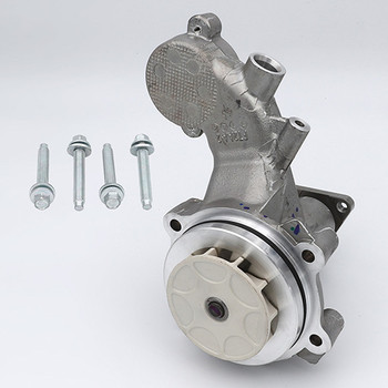
While the radiator and intake manifold were removed it was a good time to replace my stock cooling fan/shroud with a GT500 unit, and replace my water pump with a Ford Performance Water Pump from Capaldi Racing.
 shopcapaldiracing.com
 View attachment 73481
With all these cooling upgrades I wanted to be able to monitor my temps too, so I bought a Ford Performance LS Gauge Pod and AutoMeter Spek-Pro gauges. I found that this pod and these gauges don't quite want to play well together, the pod puts the gauges so close together that the bezels overlap, and the mounting arrangement for the gauges doesn't match the pod either, it was time for some more improvising. After a bit of reworking the inside of the pod to let the outer gauges move over a hair more, and by filing each bezel flat at the points of contact I was able to get my water, oil, & transmission temp gauges into the pod. (sorry, no pics of final installation yet. My oil temp gauge had to go back to AutoMeter)
I was able to adapt the gauges to the mounts in the pod by epoxying a spacer block with threaded holes to the back of each gauge.
.jpg")

The pod is a dark gray color and didn't quite match my dash. Some SprayMax 2K in satin black is a lot tougher than regular rattle-can stuff and made a decent match... And, I couldn't help attempting to colorize the "Ford Racing"' logo too, fair but not excellent results with the white.

I tapped the water outlet on the driver side cyl. head for a water temp sensor:

The Mishimoto sandwich plate has 1/8 NPT ports but to use the hot side port for temp sensor I had to clock the sandwich plate at an angle to prevent interference with the alternator.

Ran the lines across the car and back to the cooler

A spacer and long bolt to route lines high enough to clear the anti-roll bar

I added a transmission oil temp gauge too, It's installed and wired up, but have yet to find a good way to attach sensor to the transmission. I'm not feeling great about using the drain plug location as the sensor will extend downward from there. Looks pretty vulnerable being so low. At some point I probably will want a transmission cooler and a 90° fitting coming from there to a cooler would be a bit less susceptible to taking a hit. At the moment I have a functional undercar ambient temp gauge instead! (gotta have a sensor pugged in or the gauge flashes)
I've seen it read 130°
I had the bumper cover off so I finally got around to installing a front tow hook. I didn't realize it at the time but I think I was able to get one of the last available Blowfish Racing units
(pics in above post).While the radiator and intake manifold were removed it was a good time to replace my stock cooling fan/shroud with a GT500 unit, and replace my water pump with a Ford Performance Water Pump from Capaldi Racing.
5.2L "GEN 2" WATER PUMP KIT M-8501-M52A
Capaldi Racing Ford performance parts authorized distributor.
shopcapaldiracing.comView attachment 73481
With all these cooling upgrades I wanted to be able to monitor my temps too, so I bought a Ford Performance LS Gauge Pod and AutoMeter Spek-Pro gauges. I found that this pod and these gauges don't quite want to play well together, the pod puts the gauges so close together that the bezels overlap, and the mounting arrangement for the gauges doesn't match the pod either, it was time for some more improvising. After a bit of reworking the inside of the pod to let the outer gauges move over a hair more, and by filing each bezel flat at the points of contact I was able to get my water, oil, & transmission temp gauges into the pod. (sorry, no pics of final installation yet. My oil temp gauge had to go back to AutoMeter)
I was able to adapt the gauges to the mounts in the pod by epoxying a spacer block with threaded holes to the back of each gauge.
The pod is a dark gray color and didn't quite match my dash. Some SprayMax 2K in satin black is a lot tougher than regular rattle-can stuff and made a decent match... And, I couldn't help attempting to colorize the "Ford Racing"' logo too, fair but not excellent results with the white.
I tapped the water outlet on the driver side cyl. head for a water temp sensor:
The Mishimoto sandwich plate has 1/8 NPT ports but to use the hot side port for temp sensor I had to clock the sandwich plate at an angle to prevent interference with the alternator.
Ran the lines across the car and back to the cooler
A spacer and long bolt to route lines high enough to clear the anti-roll bar
I added a transmission oil temp gauge too, It's installed and wired up, but have yet to find a good way to attach sensor to the transmission. I'm not feeling great about using the drain plug location as the sensor will extend downward from there. Looks pretty vulnerable being so low. At some point I probably will want a transmission cooler and a 90° fitting coming from there to a cooler would be a bit less susceptible to taking a hit. At the moment I have a functional undercar ambient temp gauge instead! (gotta have a sensor pugged in or the gauge flashes)
I've seen it read 130°
Last edited:
- Thread starter
- #13
One of the major reasons for this round of upgrades was to improve the intercooling capacity of my supercharged engine. I know there's not a lot of love for forced induction among the track car purists here and I understand why, more now than ever, but this wasn't meant to be a purely track driven car. I installed my supercharger before I got the track bug and still enjoy street driving the car with it, but on the track I was asking the intercooler do more than it was capable of. To alleviate heat soak under track conditions I replaced every component in the system. The intercooler in the manifold is limited by the physical space available so I needed a better flowing unit to do much more, and ordered what I hoped would be a much upgraded intercooler from J2Fabrication. The story of that experience needs it's own thread, let me just say that after waiting over 8 months I opted for another one from VMP that should flow better than my original Roush supplied unit on both the air and water sides:
.jpg")
.jpg")


.jpg")
To feed this as much cold water as possible I wanted to plumb my new system with 1-1/4" hose. It didn't take long to realize that this size hose was difficult to bend where I needed without kinking and I wanted to minimize the use of flow restricting fittings. This size hose also has a large outside diameter and will not fit easily into some places. I started to use aluminum tubing in the tightest areas and ultimately ended up fabricating tubing for the entire system except for 2 lengths of hose between the chassis and engine to allow movement.
VMP also supplied 90° manifold tubes with a 1" hose barb end:
.jpg")
The original Roush tubes were closer to 45° so even with the VMP tube's ability to swivel, plumbing routing was gonna be an awkward proposition. And, I would need to adapt from 1" to 1-1/4" somewhere.

I'm a little surprised that VMP doesn't have something closer to the installation it's parts are intended to upgrade, and I couldn't find anybody else that makes hardware that fits where I wanted, so a custom modification of the modification parts was in order. I thought it would be a neat and more compact solution to have a 45° -20AN fitting mounted directly to the upper manifold connection, a straight -20AN would work nicely for the lower tube. I found a -20AN 45° to 1" NPT fitting, but how to tap for 1'NPT???
I pressed out the steel tube from the VMP manifold tube (steel in this location has been noted to have corrosion issues too) removed the flange ring, and split the remaining fitting to allow taping of the front half without boring through the entire thing. I needed the back half to be intact where the O-rings on transfer tubes seat, carrying coolant to the intercooler (inside dia.).
A 45° chamfer on the mating surfaces is for welding the parts back together:
.jpg")
.jpg")
After tapping, the 2 halves were welded back together and turned on a lathe for a nice clean look. Just enough threads for the 1" NPT fitting:
.jpg")
The NPT fitting had too many threads so after cutting some off it's ready to assemble. Used sealant in the threads to assure a leak-proof assembly:
.jpg")
Made a new stainless steel flange ring, the final result:
I had to turn down the heads of the attach bolts slightly to clear the fitting, but everything fits well
.jpg")
This eliminated the need to adapt size from 1" and let me use aluminum tubing here too instead of hose.

I like tubing over hose for a custom installation like this, I had mounting tabs welded to sections of tubes where needed to use existing fasteners for support, a simpler and cleaner looking method than fooling with clamps, standoffs, brackets, zip-ties, etc.
Prettier Too!!!
.jpg")
.jpg")
.jpg")
.jpg")
To feed this as much cold water as possible I wanted to plumb my new system with 1-1/4" hose. It didn't take long to realize that this size hose was difficult to bend where I needed without kinking and I wanted to minimize the use of flow restricting fittings. This size hose also has a large outside diameter and will not fit easily into some places. I started to use aluminum tubing in the tightest areas and ultimately ended up fabricating tubing for the entire system except for 2 lengths of hose between the chassis and engine to allow movement.
VMP also supplied 90° manifold tubes with a 1" hose barb end:
The original Roush tubes were closer to 45° so even with the VMP tube's ability to swivel, plumbing routing was gonna be an awkward proposition. And, I would need to adapt from 1" to 1-1/4" somewhere.
I'm a little surprised that VMP doesn't have something closer to the installation it's parts are intended to upgrade, and I couldn't find anybody else that makes hardware that fits where I wanted, so a custom modification of the modification parts was in order. I thought it would be a neat and more compact solution to have a 45° -20AN fitting mounted directly to the upper manifold connection, a straight -20AN would work nicely for the lower tube. I found a -20AN 45° to 1" NPT fitting, but how to tap for 1'NPT???
I pressed out the steel tube from the VMP manifold tube (steel in this location has been noted to have corrosion issues too) removed the flange ring, and split the remaining fitting to allow taping of the front half without boring through the entire thing. I needed the back half to be intact where the O-rings on transfer tubes seat, carrying coolant to the intercooler (inside dia.).
A 45° chamfer on the mating surfaces is for welding the parts back together:
After tapping, the 2 halves were welded back together and turned on a lathe for a nice clean look. Just enough threads for the 1" NPT fitting:
The NPT fitting had too many threads so after cutting some off it's ready to assemble. Used sealant in the threads to assure a leak-proof assembly:
Made a new stainless steel flange ring, the final result:
I had to turn down the heads of the attach bolts slightly to clear the fitting, but everything fits well
This eliminated the need to adapt size from 1" and let me use aluminum tubing here too instead of hose.
I like tubing over hose for a custom installation like this, I had mounting tabs welded to sections of tubes where needed to use existing fasteners for support, a simpler and cleaner looking method than fooling with clamps, standoffs, brackets, zip-ties, etc.
Prettier Too!!!
Last edited:
Dave_W
Cones - not just for ice cream
Beautiful sano work. Wondering if using an AN ORB fitting instead of NPT would have been easier to fit to the VMP flange and marginally more reliable, as the ORB fitting uses an o-ring instead of the taper interference of NPT to seal - ORB might need less thread engagement to the flange. Just a thought for version 2 if you ever need it.
- Thread starter
- #15
Thanks!Beautiful sano work. Wondering if using an AN ORB fitting instead of NPT would have been easier to fit to the VMP flange and marginally more reliable, as the ORB fitting uses an o-ring instead of the taper interference of NPT to seal - ORB might need less thread engagement to the flange. Just a thought for version 2 if you ever need it.
an ORB fitting wouldn't work because it would be sealing against the mounting flange ring:

which is sandwiched between these parts:

The NPT threads are tapped just deep enough to torque up and leave a gap under the NPT fitting that's wide enough for the ring, allowing the fitting assembly to be swiveled as needed.
Sealant applied to threads for reliable seal.
Hope I never need a version 2 though!!
Last edited:
- Thread starter
- #16
The intercooler pump I was using was the '13-'14 GT500 pump,. On the street it's adequate for most conditions, providing about 9 GPM of flow as part of a 3/4" system. Not quite up to the demands of track use though. According to the Department of Boost's numbers, with the upgraded intercooler port size and plumbing, their Titanic H/E, and POWA pump I should be seeing around 23.5 GPM flow now. Coupled with a larger Heat exchanger and Intercooler core size I should realize a dramatic improvement in the control of heat soak and much faster recovery times if there are still issues.
To avoid this much flow from creating turbulence in the the degas tank and aerating the water entering the pump a parallel bypass circuit is necessary. This also allows me to retain the existing tank with it's 3/4" inlet/outlet while the main flow remains at 1-1/4"


The POWA Pump is quite a bit larger than my previous pump and comes with a mounting bracket and plumbing from the pump to H/E intended for mounting it below the bumper bar on the outer bolts like this:

This configuration interfered with my brake cooling duct, and because my fog lamps were getting relocated from the upper grille to the lower valance corners the pump would be occupying the new lamp location too, so I fabricated a bracket and spacers to mount the pump higher and farther aft on the frame rail:
.jpg")

This new location along with the plumbing to match provided enough room for the pump, fog lamp, and brake cooling duct to play well together:


The rest of the intercooler plumbing:
.jpg")


Just one last thing. It seems that when modifying things, often a solution creates a new problem. Case in point... while installing all this new plumbing, and ensuring there would be clearance for the blower belt I realized I now had extreme difficulty accessing the belt tensioner with standard tools. Custom wrench for a custom installation was needed.


Ready for another track day!!!
_3_(1)_2.jpg")
To avoid this much flow from creating turbulence in the the degas tank and aerating the water entering the pump a parallel bypass circuit is necessary. This also allows me to retain the existing tank with it's 3/4" inlet/outlet while the main flow remains at 1-1/4"
The POWA Pump is quite a bit larger than my previous pump and comes with a mounting bracket and plumbing from the pump to H/E intended for mounting it below the bumper bar on the outer bolts like this:
This configuration interfered with my brake cooling duct, and because my fog lamps were getting relocated from the upper grille to the lower valance corners the pump would be occupying the new lamp location too, so I fabricated a bracket and spacers to mount the pump higher and farther aft on the frame rail:
This new location along with the plumbing to match provided enough room for the pump, fog lamp, and brake cooling duct to play well together:
The rest of the intercooler plumbing:
Just one last thing. It seems that when modifying things, often a solution creates a new problem. Case in point... while installing all this new plumbing, and ensuring there would be clearance for the blower belt I realized I now had extreme difficulty accessing the belt tensioner with standard tools. Custom wrench for a custom installation was needed.
Ready for another track day!!!
Last edited:
Wow, this is really nice work! Beautiful car
ChrisM
Mostly harmless.
That is wild. Really impressive work and that exchanger is massive. Good luck!
Amazing work, really impressive.
- Thread starter
- #20
Thank you!Amazing work, really impressive.
Now I just need to validate the effectiveness of all this. I'll be testing things out at Sonoma this weekend.
TMO Supporting Vendors


Similar threads
- Replies
- 0
- Views
- 242
