The Mustang Forum for Track & Racing Enthusiasts

Taking your Mustang to an open track/HPDE event for the first time? Do you race competitively? This forum is for you! Log in to remove most ads.

  • Welcome to the Ford Mustang forum built for owners of the Mustang GT350, BOSS 302, GT500, and all other S550, S197, SN95, Fox Body and older Mustangs set up for open track days, road racing, and/or autocross. Join our forum, interact with others, share your build, and help us strengthen this community!

Steering Wheel Question

This site may earn a commission from merchant affiliate links, including eBay, Amazon, and others.

Tucson 302

2013 Black LS #439
Any 2013 owner changed out the steering wheel for a racing wheel? If so without the buttons that are on the wheel is there a way to clear the warning messages that pop up?
 

skwerl

tree hugger
51
0
There is an 'ok' button on the radio as well as on the steering wheel. Press the center of the right side tuning knob.
 

Tucson 302

2013 Black LS #439
skwerl said:
There is an 'ok' button on the radio as well as on the steering wheel. Press the center of the right side tuning knob.

Thanks I didn't know that, that will work for now but eventually the radio is coming out too
 
Last I knew if you replaced the wheel with a race wheel, you will need to remove the clock spring, which contains the steering wheel position sensor. Once you loose the position sensor you will have all kinds of advance track issues. The way to resolve that is with the ford racing abs module.
 

Tucson 302

2013 Black LS #439
06mach1 said:
Last I knew if you replaced the wheel with a race wheel, you will need to remove the clock spring, which contains the steering wheel position sensor. Once you loose the position sensor you will have all kinds of advance track issues. The way to resolve that is with the ford racing abs module.

My AED tune already turned off traction control and advancetrack so I already get those annoying warning messages and I have the 302S ABS module going in this weekend. I am glad I can close them with the radio button which I will keep until I put in a data logger next month so I can see my oil temps
 

steveespo

Lord knows I'm a Voodoo Child
Moderator
4,015
1,959
Exp. Type
W2W Racing
Exp. Level
10-20 Years
Cookeville TN
06mach1 said:
Last I knew if you replaced the wheel with a race wheel, you will need to remove the clock spring, which contains the steering wheel position sensor. Once you loose the position sensor you will have all kinds of advance track issues. The way to resolve that is with the ford racing abs module.
Latest ABS module still gives all the warnings about advance trac and brake system. Not much you can do but tape over the lights. Does not hurt the way the car performs at all. Remember without clockspring you have no Advance Track functions at all.
Steve
 

PaddyPrix

If breakin' parts is cool, consider me Miles Davis
728
1,088
Exp. Type
Time Attack
Exp. Level
Under 3 Years
San Diego
Old thread, wise fwom yow gwave!

It'd seem that there stereo ok/directional no longer works on the s550, or at least when the backing stereo, lcd, and cd player have been removed.

So let's say that one no longer has a stereo, and one no longer has a stock steering wheel?

IMG_20200830_141146.jpg

Looks like the right side wiring goes to the back and then fused with the left, and once into the clock spring, goes down to even less pins. Does that mean that it's a digital signal instead of an analog one? Having it constantly tell me that I have 45 miles of fuel left at 3/4 a tank would drive me crazier than I already am.
 

PaddyPrix

If breakin' parts is cool, consider me Miles Davis
728
1,088
Exp. Type
Time Attack
Exp. Level
Under 3 Years
San Diego
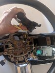
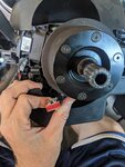
Actually, I think I'm getting closer, tracing out the pins using staples in the tiny holes on the right side, going to the end of the clock spring harness that doesn't go into the console, but to the wire running along the bottom.

IMG_20200830_151725.jpg

IMG_20200830_152309.jpg

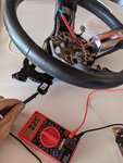
Looking at the wheel, I can only one-way forward trace, as it joins the right half signals together, and at the back looks to join the left and right pairs together. Knowing that, I'm wondering if I could then take the right ok button electronics, use some jumper wires into the lower wheel connector, and bypass the clock spring with the functionality still being there. Since I don't know which wire is which signal, I might as well trace and jump all of them which would in theory give me that full functionality.

Edit, and as luck would have it, they're split, with two on each side.

IMG_20200830_160345.jpg

If you haven't noticed, I have little knowledge of how to do electric stuff. I hope I don't accidentally fire the airbag off, because the guy I sold them to wouldn't even know where to begin 🤣
 
Last edited:

Dave_W

Cones - not just for ice cream
1,002
1,307
Exp. Type
Autocross
Exp. Level
20+ Years
Connecticut
Wiring diagram of steering wheel controls:

If you notice, the OK switch uses the same wires (BU-OG and WT-VI connecting to the clockspring through sockets 6 and 4 in connector 2274, respectively) as Phone and Voice. How the Audio Control Module knows which one you pressed is by sensing the resistance in that loop (actually the voltage drop created by the resistance). The squiggle rectangle next to each switch in the diagram is a resistor. The resistors (likely a binary-weighted resistor network) create a voltage divider, and together with the switches, make a crude Digital-to-Analog Converter (DAC).
The cruise control switches use the same voltage divider DAC style:

So, to create your own OK button, you need to measure the resistance between pins/sockets 6 and 4 in connector 2274 when no buttons on the wheel are pressed, and when only the OK button is pressed. (This is going off the 2011 wiring diagram linked to above.) Then build a circuit that creates the same resistances with your new switch. You should be able to use a common Normally Open Single-Pole Single-Throw (SPST-NO or just SPST) pushbotton switch, with the BU-OG wire connecting to a resistor that then connects to one side of the switch, the WT-VI wire connecting to the other side of the switch, and a resistor connected between both sides of the switch. The combination of the 2 resistors creates the "none pressed" resistance you measured, and the single resistor between the BU-OG wire and the switch is the "OK pressed" resistance you measured. When you press the switch, the resistor connecting both sides of the switch is taken out of the circuit by the dead short of the switch being closed.

As always, this is my interpretation of the wiring diagrams, proceed at your own risk, your mileage may vary, professional driver on a closed road, do not try at home, no user-serviceable parts inside.
 

PaddyPrix

If breakin' parts is cool, consider me Miles Davis
728
1,088
Exp. Type
Time Attack
Exp. Level
Under 3 Years
San Diego
Ah, wish I saw that earlier, but I don't know if it applies to the s550, although it should for the most part outside of perhaps colors. I realized what a pain it'd be trying to shove bare wires into female sockets, so smartened up and disassembled the clock spring, which is just thin ribbon cables. That lets me utilize all the stock harnesses and the ribbons being pretty long can then run down the steering column, and come into the back of the radio area. From there, just need to cut loose the wires you want from the harness, and should make it pretty easy to mount on the plastic switch area.

IMG_20200830_191727.jpg
 

TMO Supporting Vendors

Buy TMO Apparel

Buy TMO Apparel
Top