The Mustang Forum for Track & Racing Enthusiasts

Taking your Mustang to an open track/HPDE event for the first time? Do you race competitively? This forum is for you! Log in to remove most ads.

  • Welcome to the Ford Mustang forum built for owners of the Mustang GT350, BOSS 302, GT500, and all other S550, S197, SN95, Fox Body and older Mustangs set up for open track days, road racing, and/or autocross. Join our forum, interact with others, share your build, and help us strengthen this community!
4178.jpg

SN95 Coyote Swapped New Edge Build Thread Profile - SN95 Mustangs

What started off as a 2000 v6 slowly turning into a Coyote Swapped track car.

This site may earn a commission from merchant affiliate links, including eBay, Amazon, and others.

...I've read previous discussions about the water temp sensor location and people seemed to be split on either adding the sensor to the water neck on the driver side next to the OEM oil filter location. I want to run a combo temp/pressure sensor and the overall easiest spot is the side of the block. Will I have accurate enough readings there vs up towards the top of the engine/near the water pump?
For the side of the block, I'm assuming you mean the plug in the water jacket above the oil filter housing. This location is the first place that sees the return water from the water pump; it's probably the coolest water overall directly in the block.
 
For the side of the block, I'm assuming you mean the plug in the water jacket above the oil filter housing. This location is the first place that sees the return water from the water pump; it's probably the coolest water overall directly in the block.
Yessir, that's the location I was referring to! That makes it seem less desirable to measure from, any ideas on what a better location would be? I was thinking about tapping the water neck like mentioned in other posts however I wasn't sure if that would be the best place to put a pressure sensor. I guess I could potentially tap that and also run a separate pressure sensor on the side of the block
 
what was the final verdict on timing chain, guides, tensioners, etc.?
I'll grab you the list of parts I purchased for it today, I'm planning to get everything installed over the next couple weeks. Here's email correspondence I had with FRPP with FRPP's response in bold.

Here is my current parts list, please let me know what you think I should add or swap:

  • GT350 primary timing chains - M-6004GT350PC
  • Boss 302 tensioners w/ primary guides - M-6266-M50B
  • Tensioner arms - CR3Z-6K255-AOEM
  • Cam phaser filters - 9L8Z-6C683-A
What I'm trying to figure out:

  1. Is there a recommended secondary timing chain for road racing? No, the sec tensioners in the Gen3 engine will work.
  2. Is the GT350 primary timing chain the best option? Yes, it’s “pre-stressed” so no further stretching will occur.
  3. Is there anything else I should replace while I'm already there? I'm replacing the Oil pump gears and crank sprocket with ones from Boundary. Oil pump gears and crank sprocket are good ideas. One other change would be the GR3Z-6256-A intake phasers. These are a “low-leak” phaser allowing for better stability at higher RPM.
  4. Are the bolts reusable or will I need new bolts? Replace the cam phaser bolts and damper bolt. Boss tensioners require a longer bolt that what is used in Gen3 engine.
 
Primary timing chains: M6004GT350PC
Secondary timing chains (x2): BR3Z-6268-A
Boss 302 Timing Chain tensioner kit: M-6266-M50B
Camshaft Seal (x2): FT4Z-6C262-A
Timing chain guide: JL3Z-6B274-B
Timing chain guide: JL3Z-6M256-A
Cam intake phaser sprocket: GR3Z-6256-A
Cam phaser filter: 9L8Z-6C683-A
Intake cam phaser bolts: ARP 256-1003
Exhaust cam phaser bolt (need two): JR3Z-6279-A
Harmonic Balancer Bolt: ARP 156-2502

New seals (front main, rear main, timing, water pump, etc)

I believe that's everything I purchased, let me know if you have any questions!

Edit: Added the exhaust phaser bolt and clarifications
 
Last edited:
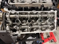
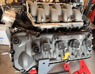
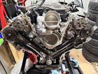
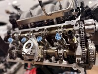
A bit of a progress update, I've ordered all parts, cleaned the engine, changed the oil pump and gears, timed the engine (sanity checking again later today), and today I will be installing the AED crank scraper and the now clearanced oil pan. If everything goes well I should be installing the engine into the car later this week.

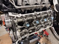
One thing I should have noticed before getting into everything is that the exhaust phasers on the Gen 3 use a single bolt (JR3Z-6279-A). I ended up getting 3 as I messed up the torquing process on the driver side..whoops! I highly recommend getting the tool to lock the cams out (keep in mind the gen 3 may use a different lockout tool than the earlier gens), my wife and I struggled to torque the passenger side but the drivers side was simple as can be because of the tool. Keep in mind that to install the lockout tool on the passenger side you will need to rotate the passenger side cams slightly so the tool can slide on. Once you've installed the new secondary timing tensioner, intake cam filter, chain, and torqued everything down on the passenger side you will need to rotate it back to the correct position to make timing easier.
I missed grabbing pics with the front cover off but the engine is looking as healthy as can be with no sparkles at all in the oil pan, just some used oil. The drivers side looks brand new while the passenger side has a healthy golden glow.

There's a whole lot of work ahead bit if anyone has any questions or would like to see something specific please let me know!

26-04-15 20-32-27 3406.jpg

C26-04-14 16-21-42 3389.jpg
 
Have you ever finished a job and then found you used the wrong bolt? In my previous post I mentioned that I screwed up the torquing process for the driver side exhaust phaser bolt. Imagine the surprise on my face when my wife hands me the new, still in packaging, exhaust phaser bolt I purchased to replace my mistake... Yupp. I disassembled the valve covers and timing cover once more, replaced the exhaust phaser bolt and torqued it correctly, and got the engine put back together once more. At least I grabbed a few missing pictures this time.

IMG_3509.jpg
IMG_3511.jpg
IMG_3512.jpg


The alternator, engine wire harness, clutch/flywheel, and bellhousing are now installed and looking great!. Some new issues did appear after installing the bellhousing:
  1. The oil pan completely blocks the clutch cable, leaving only ~1" of space between where the clutch cable sits against the bellhousing and the back of the oil pan.
  2. The passenger side upper exhaust tube makes contact with the bellhousing's starter pocket (the sphere where the starter nose cone sits).
Looking at the oil pan, I would have to significantly modify it to work with a clutch cable so I'm looking at hydraulic options. I've reached out to Silver Sport Transmissions ad Modern Driveline to see if they have a kit they would recommend to go with the TKX and would fit my setup or if I am going to have to put together something custom.
The exhaust will be an easier fix, I probably just need to get a real metal mallet or an exhaust dimpler from Summit (https://www.summitracing.com/parts/sum-dinger1750).

Parts combo I'm having issues with:
BBK Coyote Swap long tube headers (16340)
Ford Performance Road Race oil pan (M-6675-M52RR)
Quicktime TKX bellhousing (RM-6081)

I've realized over the past couple of weeks how massive of a project this swap is but I'm so excited to dig in deeper! For now I'm going to switch back to finalizing the wiring, painting the brake calipers, putting in a new hydroboost (initially a v6 with a vacuum booster, the hydroboost I put in has always felt a smidge squishy), cleaning the engine bay, and figuring out how to best mount the control pack. Lets see what all I can get done before I can properly mount the headers!

A question for anyone reading, does anyone happen to know how the thickness of the OEM Ford exhaust gasket? The gaskets alone won't solve my problem but the spacing they provide will at least help a smidge.
 
It's been a few months since my last post but a good bit of progress has been made! In the last post I needed to find a solution for the clutch cable and clearancing the header primary tube.

I clearanced the primary tube where it was making contact with the bellhousing's starter pocket and Summit's tool helped make quick and precise work of it. I was genuinely impressed.

I moved the Mustang into my garage and started on the front end disassebly and cleaning. This involved removing all of the front suspension/steering components and the factory k-member. While there is 200k on the body, both the body and frame are in excellent condition. I gotta hand it to those greasy Arizona roads for protecting the chasis so thoroughly! I also painted the calipers with POR15 high temp paint (44318) and while they look decent, I would NOT recommed it. You need to cure the paint at 400f for a minimum of 2 hours and I stupidly applied the paint to assembled calipers thinking the paint would mostly cure and I could cure it the rest of the way via heavy braking. It turns out the paint was as soft as ever after 2 days of waiting, I contacted POR 15 who recommend using their other claiper paint instead of this paint, and while hitting the calipers with a heat gun and propane torch helped harden the paint a bit it's still a smidge soft and leaves residue on your hands/gloves. Gross.

Once the cleaning was done I leveled the car and started working on the Maximum Motorsports k-member. I don't know what kind of luck I had that day but the k-member did not need to be adjusted at all, it was perfectly straight and centered. I double checked each plumb bob and re-measured to be sure but it all lined up perfectly. From here I drilled two holes through the k-member and frame on each side to allow me to re-center the k-member if and when it ever needs to be removed.

From here I dropped the k-member, installed the trans, raised the car as high as I could on the quickjacks, and with the helf from the wife I lifted the front end of the car, tilting it just enough to allow the engine assembly to slide in through the wheel well. Unfortunately, the engine lift brackets I have interefered with the driver side frame to the point where I ended up having to sett the front of the car on bricks and the rear wheels on a set of dollies to get the body low enough to get the lift bracket installed. We lifted the engine, quickly installed the forward offset motor mounts and exhaust, raised the car back up to make room for the k-member, and attempted to get the k-member installed.
We weren't able to get the engine to sit on both studs due to interferance from a primary tube on the passenger side. To get around this I had to remove the passenger side engine mount, very loosely install it on the k-member, move the k-member into position and carefully install the motor mount back onto the engine. Keep in mind, once the the exhaust is installed, only the passenger side motor mount bolts are accesible while the drivers side is not.
Finally, with a little more elbow grease and the holes I drilled and tapped previously, we were able to lift the engine and k-member into position and get it all torqued down.

The engine is finally in!!

I'm surprised how offset the engine is to the passenger side of the engine bay. After looking at many pictures/videos and making a few calls I was able to determine that this is the expected position of the engine when installed. The only clearance issue I have is the bracket that covers the HPFP on the Gen 3 passenger valve cover. Removing the cover gives a comfortable amount of clearance back.

To resolve the clutch cable issue I was running into I ended up purchasing Modern Driveline's "Stealth" hydraulic clutch kit and now have it mostly installed. I did run into one major issue with the kit, apparently not all pedal hanger assemblies have a built-in stud on the bottom right that runs through the firewall for the hydroboost to bolt to. The kit requires you to use bolt a bracket to the bottom two studs, which wouldn't work at all in my situation. Thankfully the weld on the hanger's stud wasn't too strong and I was able to pop the stud out using a balljoint removal tool. With the stud gone, I was able to insert a m8 bolt and get the bracket and assembly properly torqued down. All that's left here is adjusting and installing the lines.


Next steps:
Tackle the front suspension
Fix a crushed brake line
Wire in the new front and rear body harnesses, ABS, and control pack
Plumb the fuel, power steering, and oil systems
Fix a leak on the differential and install the diff cooler
And everything else inbetween!
 
Top