I had posted in the thread on the reverse camera that I would post a solution to the exhaust valve. I will make this a multi-part post offering an overview and multiple solutions ranging from very cheap to more involved and elegant but also a tiny bit more expensive.
So first a quick overview of the circuit we are dealing with:

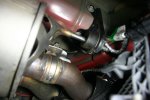
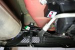
The exhaust valves in the back are solenoids. The PCM controls when the exhaust valves are opened or closed. As we all know, it does what it wants and sometimes at the most inopportune time. The PCM sends a very low voltage and amperage signal to the coil of the solenoids to activate them. This activation allows a larger current to flow from the battery junction box through to the solenoid actuator that opens and closes the exhaust valve - upper right.
Quick explanation of the Grimm Exhaust Valve Defeat Module. The module was designed for people who install exhaust systems without exhaust valves. When you unplug the exhaust valve at connector C4466 and C4467, it creates an open circuit that the PCM sees on pin 11 which is the line that the PCM uses to control the exhaust valves. The PCM detects a fault and throws a DTC code. So the Grimm solution tricks the PCM into believing that there are exhaust valve solenoids out there by using a resistor with the same resistance as the original exhaust valve solenoid coils. Obviously you need 2 because they are plugged into the wiring harnesses where the 2 exhaust valves used to be.
I believe it was VoodoBoss who sourced the harness extensions which are shown between C345 and C4467 on the driver side and C346 and C4466 on the passenger side. The Ford service part numbers for these extensions are:
FR3Z-14A411-H for the drivers side
FR3Z-14A411-J for the passenger side
FR3Z-14A411-J is no longer available but both are exactly the same. Only difference is that FR3Z-14A411-H is a little bit longer. The harness (ea) cost approx. $15 So with the Grimm modules and 2 extension harnesses you are in for approx $70
I believe that it was VoodoBoss who cut the chase and said basically, the only thing that “we” need is the ability to make sure that the exhaust valves stay closed on a track with noise restrictions. My paraphrase
So here is a quick and dirty solution with two variations. Variation 1 costs less then $15 and about an hour of work but requires cutting into a wiring harness. Variation 2 costs around $60 and will require about 1-2 hours worth of work but you will not have to cut into any wire harness. It’s a plug and play option that when unplugged, returns the wiring to the way it came from the factory. Both use a simple toggle switch with two positions, OEM operation and exhaust valve closed. You can always open the exhaust valve via the switches on your steering wheel / menu in OEM mode or via the center console if you have the electronics package.
So variation 1 for less then $15
Bill of Material
-------------------
12v/15amp toggle switch
8 feet of 16 gauge wire (I would use red since its power on both leads)
This will require splicing into a wiring harness.
If you follow the leads from pin 2 on the exhaust valve solenoids, you see that this is where the high amperage power enters the solenoids. If you trace the leads up to the Battery Junction Box, you will see the wire runs through an inline connector C215. Inline connectors consist of a male and female connector. It’s simply an inline connector. Here is the connector info and the pin-outs:
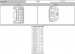
You can see from the circuit above that the wire we are interested in is on pin 2. The good part of splicing into this connector is that it’s in the passenger compartment (no weather or heat issues) and is located behind the kick panel in the passenger foot well.
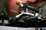
Here is a picture of where it is located:

So what you need to do is find the connector, strip back the insulation that wraps the harness at the connector, find pin 2 – it will be the violet wire with a brown strip – same on both male and female connector. Cut the wire (either side) and solder in a 4ft piece of 16 gauge of wire to each cut end and seal up the splice with heat shrink tubing. Re-wrap the connector.
Create a harness by wrapping your 2 spliced in wires with electrical tape. Route your newly created harness back behind the dash board over the sun glass tray or where every you are mounting the switch.
I would find a small plastic hobby box that fits in the back of the sun glass tray and mount the switch there.
The switch will have 3 contacts on it. Check it with a VOM but typically the center is common and each of the 2 outside contacts are either on or off. Solder one wire to the center and one to one of the end contacts. Mount the switch, DONE!
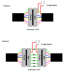
Here is a simple schematic of the circuit you are adding:
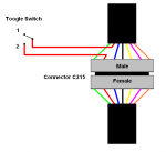
Here is what it is doing:
Switch in position 2 above is OEM mode. Nothing has changed. The power flows down from the Battery Junction Box through connector C215 normally just as Ford designed it. Exhaust valve does whatever the PCM wants it to do.
Switch in position 1 breaks the line and does not allow the power to flow to the exhaust valves. The PCM see’s the actuator coils (nothing has changed on that end) and switches away as it wants but nothing happens because the higher power needed to run the actuator isn’t there. PCM thinks that it’s either open or closed and thus no DTC codes but in reality the valves remain closed. With no high power flowing to the exhaust valve, they remain closed.
And you control it from the dash (or where ever you mount the switch) without having to do a thing like switch harnesses, or plug in resistors.
You could technically, keep the switch in OEM mode and as you approach the station on the track that measures sound levels, switch the vales off and when you pass the station turn the vales back on
In the next post, I will show you how you can do the exact same thing as version 1 here but without having to splice into the harness. It will cost a bit more and required a little more work but I believe is worth it.
So first a quick overview of the circuit we are dealing with:

The exhaust valves in the back are solenoids. The PCM controls when the exhaust valves are opened or closed. As we all know, it does what it wants and sometimes at the most inopportune time. The PCM sends a very low voltage and amperage signal to the coil of the solenoids to activate them. This activation allows a larger current to flow from the battery junction box through to the solenoid actuator that opens and closes the exhaust valve - upper right.
Quick explanation of the Grimm Exhaust Valve Defeat Module. The module was designed for people who install exhaust systems without exhaust valves. When you unplug the exhaust valve at connector C4466 and C4467, it creates an open circuit that the PCM sees on pin 11 which is the line that the PCM uses to control the exhaust valves. The PCM detects a fault and throws a DTC code. So the Grimm solution tricks the PCM into believing that there are exhaust valve solenoids out there by using a resistor with the same resistance as the original exhaust valve solenoid coils. Obviously you need 2 because they are plugged into the wiring harnesses where the 2 exhaust valves used to be.
I believe it was VoodoBoss who sourced the harness extensions which are shown between C345 and C4467 on the driver side and C346 and C4466 on the passenger side. The Ford service part numbers for these extensions are:
FR3Z-14A411-H for the drivers side
FR3Z-14A411-J for the passenger side
FR3Z-14A411-J is no longer available but both are exactly the same. Only difference is that FR3Z-14A411-H is a little bit longer. The harness (ea) cost approx. $15 So with the Grimm modules and 2 extension harnesses you are in for approx $70
I believe that it was VoodoBoss who cut the chase and said basically, the only thing that “we” need is the ability to make sure that the exhaust valves stay closed on a track with noise restrictions. My paraphrase
So here is a quick and dirty solution with two variations. Variation 1 costs less then $15 and about an hour of work but requires cutting into a wiring harness. Variation 2 costs around $60 and will require about 1-2 hours worth of work but you will not have to cut into any wire harness. It’s a plug and play option that when unplugged, returns the wiring to the way it came from the factory. Both use a simple toggle switch with two positions, OEM operation and exhaust valve closed. You can always open the exhaust valve via the switches on your steering wheel / menu in OEM mode or via the center console if you have the electronics package.
So variation 1 for less then $15
Bill of Material
-------------------
12v/15amp toggle switch
8 feet of 16 gauge wire (I would use red since its power on both leads)
This will require splicing into a wiring harness.
If you follow the leads from pin 2 on the exhaust valve solenoids, you see that this is where the high amperage power enters the solenoids. If you trace the leads up to the Battery Junction Box, you will see the wire runs through an inline connector C215. Inline connectors consist of a male and female connector. It’s simply an inline connector. Here is the connector info and the pin-outs:

You can see from the circuit above that the wire we are interested in is on pin 2. The good part of splicing into this connector is that it’s in the passenger compartment (no weather or heat issues) and is located behind the kick panel in the passenger foot well.
Here is a picture of where it is located:

So what you need to do is find the connector, strip back the insulation that wraps the harness at the connector, find pin 2 – it will be the violet wire with a brown strip – same on both male and female connector. Cut the wire (either side) and solder in a 4ft piece of 16 gauge of wire to each cut end and seal up the splice with heat shrink tubing. Re-wrap the connector.
Create a harness by wrapping your 2 spliced in wires with electrical tape. Route your newly created harness back behind the dash board over the sun glass tray or where every you are mounting the switch.
I would find a small plastic hobby box that fits in the back of the sun glass tray and mount the switch there.
The switch will have 3 contacts on it. Check it with a VOM but typically the center is common and each of the 2 outside contacts are either on or off. Solder one wire to the center and one to one of the end contacts. Mount the switch, DONE!
Here is a simple schematic of the circuit you are adding:

Here is what it is doing:
Switch in position 2 above is OEM mode. Nothing has changed. The power flows down from the Battery Junction Box through connector C215 normally just as Ford designed it. Exhaust valve does whatever the PCM wants it to do.
Switch in position 1 breaks the line and does not allow the power to flow to the exhaust valves. The PCM see’s the actuator coils (nothing has changed on that end) and switches away as it wants but nothing happens because the higher power needed to run the actuator isn’t there. PCM thinks that it’s either open or closed and thus no DTC codes but in reality the valves remain closed. With no high power flowing to the exhaust valve, they remain closed.
And you control it from the dash (or where ever you mount the switch) without having to do a thing like switch harnesses, or plug in resistors.
You could technically, keep the switch in OEM mode and as you approach the station on the track that measures sound levels, switch the vales off and when you pass the station turn the vales back on
In the next post, I will show you how you can do the exact same thing as version 1 here but without having to splice into the harness. It will cost a bit more and required a little more work but I believe is worth it.
Last edited:
