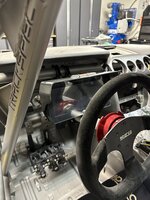
I was just about to comment that!Knees weak, arms are heavy
- Welcome to the Ford Mustang forum built for owners of the Mustang GT350, BOSS 302, GT500, and all other S550, S197, SN95, Fox Body and older Mustangs set up for open track days, road racing, and/or autocross. Join our forum, interact with others, share your build, and help us strengthen this community!
You are using an out of date browser. It may not display this or other websites correctly.
You should upgrade or use an alternative browser.
You should upgrade or use an alternative browser.
S550 Honey Badger GT350 Build Build Thread Profile - S550 Mustangs
- Thread starterhoneybadger
- Start date
This site may earn a commission from merchant affiliate links, including eBay, Amazon, and others.
More options
Who Replied?- Thread starter
- #262
made some good progress last night - got the trans/diff coolers mounted in the rear
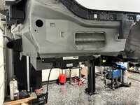
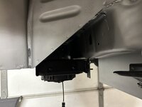
and also got my rear quarter window solution figured out. 1/8in lexan that's wrapped in CF vinyl screwed into some rivet nuts (with some plastic spacers to get the height right) This means they're removable and offer a good spot to install the airjacks connection on the passenger and the naca duct for the chillout system intake
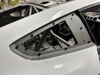
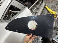
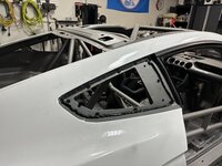
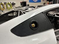
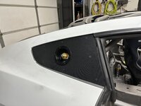
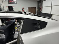
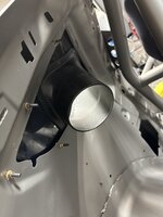


and also got my rear quarter window solution figured out. 1/8in lexan that's wrapped in CF vinyl screwed into some rivet nuts (with some plastic spacers to get the height right) This means they're removable and offer a good spot to install the airjacks connection on the passenger and the naca duct for the chillout system intake


Fabman
Dances with Racecars
- 6,553
- 8,204
- Exp. Type
- W2W Racing
- Exp. Level
- 20+ Years
excellent.made some good progress last night - got the trans/diff coolers mounted in the rear
View attachment 87891View attachment 87890
and also got my rear quarter window solution figured out. 1/8in lexan that's wrapped in CF vinyl screwed into some rivet nuts (with some plastic spacers to get the height right) This means they're removable and offer a good spot to install the airjacks connection on the passenger and the naca duct for the chillout system intake
View attachment 87889View attachment 87888View attachment 87887View attachment 87886View attachment 87885View attachment 87884View attachment 87883
My projects always fall apart at the halfway point, when it’s time to put stuff back together. And you’re doing this….
- Thread starter
- #266
Got the diff/trans coolers and pumps mounted. Mounting the pumps underneath the car for more streamlined plumbing and likely better cooling. We'll see if I have to move to inside the rear trunk area if serviceability becomes an issue.
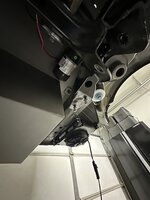
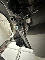
To ensure they're nice and secure, I cutout a steel plate and tacked some bolts to it. Rivet nuts would probably have been fine, but since these are hanging upside down, better safe than sorry.
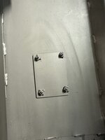


To ensure they're nice and secure, I cutout a steel plate and tacked some bolts to it. Rivet nuts would probably have been fine, but since these are hanging upside down, better safe than sorry.

Let's hope I can get it running! haThis will be the coolest and most detailed home build ever
This happens with all my other projects. The trick for me is to just harness my hyper focus on the most expensive one (this wins that by miles hahaha)My projects always fall apart at the halfway point, when it’s time to put stuff back together. And you’re doing this….
- Thread starter
- #267
- Thread starter
- #268
Well, it's been a slow couple of weeks making small bits of progress kind of all over the place. But today I finally finished the engine up. It's ready to drop on the k-member.
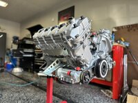
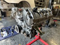
Dry sump is installed. The dailey pump and pan is a pure work of art. Absolute dime piece of engineering and CNC-machining. Will post a detailed bit about installing that as there were some surprises.
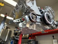
A keen eye will also notice the lack of a water pump. I'm going electric and will also have a separate post on that with all the details as I'm taking a bit of a new approach there.
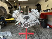
I cerakoted the cam and front engine covers - they came out great. Really love this stuff.
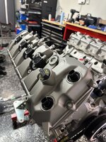
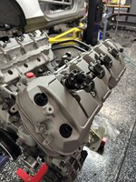
For a quick engine summary - it's mostly the same as before. We only had to re-deck the heads/block, put in new rings, balance the new CPC w/ existing rotating assembly, and install the L&M engine cams.


Dry sump is installed. The dailey pump and pan is a pure work of art. Absolute dime piece of engineering and CNC-machining. Will post a detailed bit about installing that as there were some surprises.

A keen eye will also notice the lack of a water pump. I'm going electric and will also have a separate post on that with all the details as I'm taking a bit of a new approach there.

I cerakoted the cam and front engine covers - they came out great. Really love this stuff.


For a quick engine summary - it's mostly the same as before. We only had to re-deck the heads/block, put in new rings, balance the new CPC w/ existing rotating assembly, and install the L&M engine cams.
Your not going to be able to drive that car after this. Museum piece.
Build looks to be coming along great in all aspects. Be cautious with that valve cover breather--be ready to install a remote breather can. Also, since you are on the Predator VCs, be sure to install the wiring harness with the COP pigtails routed ABOVE and over the main harness as opposed to under (and resting on the VC surface). I haven't had any confirmed issues due to this but the VCs get very hot during use and I could see this easily causing some electrical woes.
Fabman
Dances with Racecars
- 6,553
- 8,204
- Exp. Type
- W2W Racing
- Exp. Level
- 20+ Years
Now I gotta go out and look at mine...thanks for the tip!Build looks to be coming along great in all aspects. Be cautious with that valve cover breather--be ready to install a remote breather can. Also, since you are on the Predator VCs, be sure to install the wiring harness with the COP pigtails routed ABOVE and over the main harness as opposed to under (and resting on the VC surface). I haven't had any confirmed issues due to this but the VCs get very hot during use and I could see this easily causing some electrical woes.
Fabman
Dances with Racecars
- 6,553
- 8,204
- Exp. Type
- W2W Racing
- Exp. Level
- 20+ Years
Looks awesome....I'm interested to see what you do for a water pump.Well, it's been a slow couple of weeks making small bits of progress kind of all over the place. But today I finally finished the engine up. It's ready to drop on the k-member.
View attachment 88796View attachment 88795
Dry sump is installed. The dailey pump and pan is a pure work of art. Absolute dime piece of engineering and CNC-machining. Will post a detailed bit about installing that as there were some surprises.
View attachment 88794
A keen eye will also notice the lack of a water pump. I'm going electric and will also have a separate post on that with all the details as I'm taking a bit of a new approach there.
View attachment 88797
I cerakoted the cam and front engine covers - they came out great. Really love this stuff.
View attachment 88792View attachment 88793
For a quick engine summary - it's mostly the same as before. We only had to re-deck the heads/block, put in new rings, balance the new CPC w/ existing rotating assembly, and install the L&M engine cams.
Looks fantastic. Really looking forward to the Dailey dry sump install details. Are the K-member and motor mounts stock? I’m asking because I’m planning on using Steeda’s Road Race K-member and motor mounts when my redone engine with Dailey dry sump is installed. This setup should allow lowering the engine 1 to 2 inches I believe. Also, I can’t remember if you decided for sure, are you mounting the oil tank where the stock battery was located as in the GT4?Well, it's been a slow couple of weeks making small bits of progress kind of all over the place. But today I finally finished the engine up. It's ready to drop on the k-member.
View attachment 88796View attachment 88795
Dry sump is installed. The dailey pump and pan is a pure work of art. Absolute dime piece of engineering and CNC-machining. Will post a detailed bit about installing that as there were some surprises.
View attachment 88794
A keen eye will also notice the lack of a water pump. I'm going electric and will also have a separate post on that with all the details as I'm taking a bit of a new approach there.
View attachment 88797
I cerakoted the cam and front engine covers - they came out great. Really love this stuff.
View attachment 88792View attachment 88793
For a quick engine summary - it's mostly the same as before. We only had to re-deck the heads/block, put in new rings, balance the new CPC w/ existing rotating assembly, and install the L&M engine cams.
- Thread starter
- #274
Never! Going to pound the pavement as always!Your not going to be able to drive that car after this. Museum piece.
How come about the remote breather? I haven't seen anyone remote mount the vacuum regulator for the dry sump, but I also don't know anyone using a dry sumpBuild looks to be coming along great in all aspects. Be cautious with that valve cover breather--be ready to install a remote breather can. Also, since you are on the Predator VCs, be sure to install the wiring harness with the COP pigtails routed ABOVE and over the main harness as opposed to under (and resting on the VC surface). I haven't had any confirmed issues due to this but the VCs get very hot during use and I could see this easily causing some electrical woes.
I ran the 500 covers last year and didn't have an issue, but it's a good thought. The surface temps were definitely higher on these than the plastic ones. I probably need to build a motorsport grade harness. I've had so many issues with OEM harnesses - especially the VCT plugs.
I'm going to run a Pierburg CWA400 pump with their micro controller. Replaces thermostat and allows all AN plumbing. Supposedly has higher pressure than the other offerings on the marketLooks awesome....I'm interested to see what you do for a water pump.
I built a small box inside the cabin. I wanted to run a tall, narrow tank and wanted to keep the weight low. Also didn't like the idea of running the oil lines through the cabin.Looks fantastic. Really looking forward to the Dailey dry sump install details. Are the K-member and motor mounts stock? I’m asking because I’m planning on using Steeda’s Road Race K-member and motor mounts when my redone engine with Dailey dry sump is installed. This setup should allow lowering the engine 1 to 2 inches I believe. Also, I can’t remember if you decided for sure, are you mounting the oil tank where the stock battery was located as in the GT4?
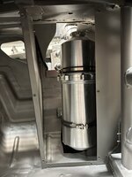
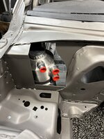
My motor mounts are the Watson lowering mounts. They replace both parts of the OEM mount and lower the engine by 1in
- Thread starter
- #275
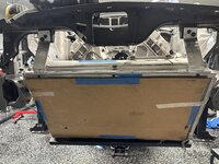
Okay, V1 of the rad mount is done. Got it at about a 42* angle, so it's got a pretty good roll to it. There's probably more if I was willing to push it all the way to the inside of the bumper, but I still want a crash bar to protect it.
As a recap, this is a "car of tomorrow" nascar radiator that bought off ebay. It was a spare and never used. It's 3in shorter than stock, but a full inch thicker and a tad wider. Ultimately, it leads to about 20% increase in capacity. if you look closely, you'll actually see it's two separate pieces. The second one is the oil cooler - a perfect replica of the radiator. It sits behind the radiator, so that will be a change from my previous FP350S setup.
I had the fittings modified by a local shop to AN. 12an for both oil connections and 16an for coolant inlet and 20an for outlet.
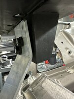
As for mounting, I chopped the front of the k-member off and welded some 1x2 tubing to it. Then reinforced that with some 1/8 flat stock that I welded over the joints. Since this now hangs as low as the lowest part of the k-member, it needed to be able to take a hit.
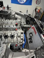
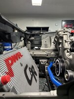
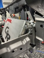
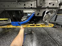
This setup did require notching the frame rail. Not my preferred method - but not end the world since this is after the 4 areas the k-member bolts. So load is much smaller. Plus, the notch is pretty tame.
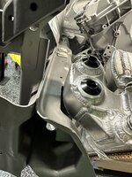
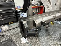
Top is mounted with AL to the upper rad support.Rivet nuts go into the tabs you see here. There are some rubber grommets in between the AL and rad support.
I also added these tabs to the back side that will have foam on them and reinforce the rad from behind in case the mounts develop some flex.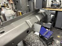
Finally, I plan to cut the blue taped part off to open the bottom up to feed the radiator (1/3 the size of the radiator face). The top will then be used for an air intake and blocked off to reduce drag.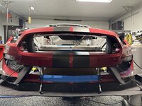
As a recap, this is a "car of tomorrow" nascar radiator that bought off ebay. It was a spare and never used. It's 3in shorter than stock, but a full inch thicker and a tad wider. Ultimately, it leads to about 20% increase in capacity. if you look closely, you'll actually see it's two separate pieces. The second one is the oil cooler - a perfect replica of the radiator. It sits behind the radiator, so that will be a change from my previous FP350S setup.
I had the fittings modified by a local shop to AN. 12an for both oil connections and 16an for coolant inlet and 20an for outlet.
As for mounting, I chopped the front of the k-member off and welded some 1x2 tubing to it. Then reinforced that with some 1/8 flat stock that I welded over the joints. Since this now hangs as low as the lowest part of the k-member, it needed to be able to take a hit.


This setup did require notching the frame rail. Not my preferred method - but not end the world since this is after the 4 areas the k-member bolts. So load is much smaller. Plus, the notch is pretty tame.


Top is mounted with AL to the upper rad support.Rivet nuts go into the tabs you see here. There are some rubber grommets in between the AL and rad support.

I also added these tabs to the back side that will have foam on them and reinforce the rad from behind in case the mounts develop some flex.

Finally, I plan to cut the blue taped part off to open the bottom up to feed the radiator (1/3 the size of the radiator face). The top will then be used for an air intake and blocked off to reduce drag.

Last edited:
Forgot about the dry sump--maybe the breather won't be an issue after all. LOVE the laydown radiator/oil cooler setup. In for more notes on that as you move forward.
- Thread starter
- #277
So, speaking of the radiator, I've been working with TracTuff on a swirl tank/header tank setup. Wondering what a swirl tank is? I was too when I embarked on this non-OEM cooling setup.
Essentially, when you go with a setup like the one I am planning (no thermostat, electric water pump, rolled radiator, all AN fittings, etc.), you need to make some adjustment (well, you should). There are some specific considerations -
1. Where will you fill up the cooling system
2. How will you remove air from the system
After really digging into this, I've discovered swirl tanks and header tanks. These are huge in the nascar world where everything is custom and using non-OEM components, but where budgets don't rival Factory support top tier race car development (prototypes, etc.)
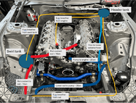
The idea is that the swirl tank intercepts the hot coolant coming out of the engine and swirls it around, separating the air, and then sends it to the rad for cooling. The bleed line is then sent to the header tank. The header tank also connects to a high point in the engine and the highest part of the radiator to help bleed air. It also has a fill line that ties into the lower radiator hose right before the water pump. This is used to fill the system and the water pump will self-bleed the system when you run it during the filling process.
The radiator cap is on the header tank - which should be mounted in the highest part of the engine bay.
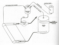
So onto my setup, I've mocked up a super, duper accurate diagram of how I plan to run my setup. Swirl tank will go where the OEM battery box/ECU were and the header tank where the OEM brake booster went. Then water pump will be near the alternator - this isn't ideal. It's primarily the result of packaging constraints due to hose size, radiator location, etc.
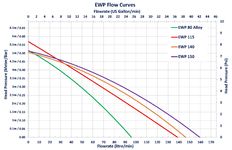
okay, so how about the water pump? I'm planning on using the Pierburg CWA400. I looked Meizre - good flow rate, but packaging is geared towards plug and play. The Craig Davies are super common and cheap, so you could buy a couple fairly easy and keep a spare on hand. However, I wasn't a huge fan of their pressure.
Here's there graph for the Craig Davies - at the max flow rate of 150L, pressure is only 0.05 bar. So it not only doesn't match the Meizre pump's flow of 208L, it's got super low pressure at high flow.
Now the Pierburg is a different story. This pump exceeds the Meizre at up to 220L flow rate. And even better, we can see that it still produces 0.55 bar at that flow rate. No idea what Meizre produces - they don't share that info (so it's probably not as impressive - but that's a guess).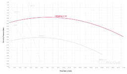
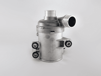
The Pierburg also has two other benefits. First, it's used as OEM equipment in german car manufacturers (BMW for example), so you know it's been thoroughly tested (BMW jokes aside, I personally trust OEM minimum requirements more than most "race" brands). https://www.tecomotive.com/en/products/CWA400.html
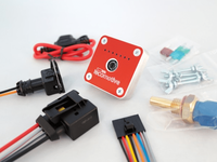
Second they offer a microcontroller called the TinyCWA that controls the pump speed based on temp. It even allows you to remove the thermostat - using the pump speed to mimic the thermostat. And it will control the fan as needed. https://tecomotive.com/store/en/tinycwa/tecomotive-tinycwa?number=T.00101.2.0.6
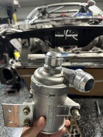
I have mine onsite - we've modified the inlet/outlet to 20 AN (the cover isn't fully seated as I am still doing a bit of machining on it).
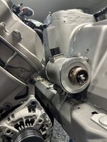
And plan to mount as such below. Motor is solid mounted using the watson mounts, so should smash into it.
Will share more on hose, plumbing, etc. once I get the tanks from TracTuff. Not ordering any of the super expensive hose bits until then. Feel free to ask questions/provide some feedback. All new ground for me
Essentially, when you go with a setup like the one I am planning (no thermostat, electric water pump, rolled radiator, all AN fittings, etc.), you need to make some adjustment (well, you should). There are some specific considerations -
1. Where will you fill up the cooling system
2. How will you remove air from the system
After really digging into this, I've discovered swirl tanks and header tanks. These are huge in the nascar world where everything is custom and using non-OEM components, but where budgets don't rival Factory support top tier race car development (prototypes, etc.)
The idea is that the swirl tank intercepts the hot coolant coming out of the engine and swirls it around, separating the air, and then sends it to the rad for cooling. The bleed line is then sent to the header tank. The header tank also connects to a high point in the engine and the highest part of the radiator to help bleed air. It also has a fill line that ties into the lower radiator hose right before the water pump. This is used to fill the system and the water pump will self-bleed the system when you run it during the filling process.
The radiator cap is on the header tank - which should be mounted in the highest part of the engine bay.

So onto my setup, I've mocked up a super, duper accurate diagram of how I plan to run my setup. Swirl tank will go where the OEM battery box/ECU were and the header tank where the OEM brake booster went. Then water pump will be near the alternator - this isn't ideal. It's primarily the result of packaging constraints due to hose size, radiator location, etc.

okay, so how about the water pump? I'm planning on using the Pierburg CWA400. I looked Meizre - good flow rate, but packaging is geared towards plug and play. The Craig Davies are super common and cheap, so you could buy a couple fairly easy and keep a spare on hand. However, I wasn't a huge fan of their pressure.
Here's there graph for the Craig Davies - at the max flow rate of 150L, pressure is only 0.05 bar. So it not only doesn't match the Meizre pump's flow of 208L, it's got super low pressure at high flow.

Now the Pierburg is a different story. This pump exceeds the Meizre at up to 220L flow rate. And even better, we can see that it still produces 0.55 bar at that flow rate. No idea what Meizre produces - they don't share that info (so it's probably not as impressive - but that's a guess).

The Pierburg also has two other benefits. First, it's used as OEM equipment in german car manufacturers (BMW for example), so you know it's been thoroughly tested (BMW jokes aside, I personally trust OEM minimum requirements more than most "race" brands). https://www.tecomotive.com/en/products/CWA400.html

Second they offer a microcontroller called the TinyCWA that controls the pump speed based on temp. It even allows you to remove the thermostat - using the pump speed to mimic the thermostat. And it will control the fan as needed. https://tecomotive.com/store/en/tinycwa/tecomotive-tinycwa?number=T.00101.2.0.6

I have mine onsite - we've modified the inlet/outlet to 20 AN (the cover isn't fully seated as I am still doing a bit of machining on it).

And plan to mount as such below. Motor is solid mounted using the watson mounts, so should smash into it.

Will share more on hose, plumbing, etc. once I get the tanks from TracTuff. Not ordering any of the super expensive hose bits until then. Feel free to ask questions/provide some feedback. All new ground for me
Fabman
Dances with Racecars
- 6,553
- 8,204
- Exp. Type
- W2W Racing
- Exp. Level
- 20+ Years
That’s prettty much the same hose routing I use as well (except no swirl pot) I also take a bleed line from the radiator and one from the water neck at the front of the head where the upper rad hose attaches. No thermostat and fill from the lower rad hose.So, speaking of the radiator, I've been working with TracTuff on a swirl tank/header tank setup. Wondering what a swirl tank is? I was too when I embarked on this non-OEM cooling setup.
Essentially, when you go with a setup like the one I am planning (no thermostat, electric water pump, rolled radiator, all AN fittings, etc.), you need to make some adjustment (well, you should). There are some specific considerations -
1. Where will you fill up the cooling system
2. How will you remove air from the system
After really digging into this, I've discovered swirl tanks and header tanks. These are huge in the nascar world where everything is custom and using non-OEM components, but where budgets don't rival Factory support top tier race car development (prototypes, etc.)
The idea is that the swirl tank intercepts the hot coolant coming out of the engine and swirls it around, separating the air, and then sends it to the rad for cooling. The bleed line is then sent to the header tank. The header tank also connects to a high point in the engine and the highest part of the radiator to help bleed air. It also has a fill line that ties into the lower radiator hose right before the water pump. This is used to fill the system and the water pump will self-bleed the system when you run it during the filling process.
The radiator cap is on the header tank - which should be mounted in the highest part of the engine bay.
View attachment 89026
So onto my setup, I've mocked up a super, duper accurate diagram of how I plan to run my setup. Swirl tank will go where the OEM battery box/ECU were and the header tank where the OEM brake booster went. Then water pump will be near the alternator - this isn't ideal. It's primarily the result of packaging constraints due to hose size, radiator location, etc.
View attachment 89025
okay, so how about the water pump? I'm planning on using the Pierburg CWA400. I looked Meizre - good flow rate, but packaging is geared towards plug and play. The Craig Davies are super common and cheap, so you could buy a couple fairly easy and keep a spare on hand. However, I wasn't a huge fan of their pressure.
Here's there graph for the Craig Davies - at the max flow rate of 150L, pressure is only 0.05 bar. So it not only doesn't match the Meizre pump's flow of 208L, it's got super low pressure at high flow.
View attachment 89027
Now the Pierburg is a different story. This pump exceeds the Meizre at up to 220L flow rate. And even better, we can see that it still produces 0.55 bar at that flow rate. No idea what Meizre produces - they don't share that info (so it's probably not as impressive - but that's a guess).View attachment 89028
The Pierburg also has two other benefits. First, it's used as OEM equipment in german car manufacturers (BMW for example), so you know it's been thoroughly tested (BMW jokes aside, I personally trust OEM minimum requirements more than most "race" brands). https://www.tecomotive.com/en/products/CWA400.html
View attachment 89030
Second they offer a microcontroller called the TinyCWA that controls the pump speed based on temp. It even allows you to remove the thermostat - using the pump speed to mimic the thermostat. And it will control the fan as needed. https://tecomotive.com/store/en/tinycwa/tecomotive-tinycwa?number=T.00101.2.0.6
View attachment 89029
I have mine onsite - we've modified the inlet/outlet to 20 AN (the cover isn't fully seated as I am still doing a bit of machining on it).
View attachment 89031
And plan to mount as such below. Motor is solid mounted using the watson mounts, so should smash into it.
View attachment 89032
Will share more on hose, plumbing, etc. once I get the tanks from TracTuff. Not ordering any of the super expensive hose bits until then. Feel free to ask questions/provide some feedback. All new ground for me
It’s worked out very well.
Dave_W
Cones - not just for ice cream
Is there a reason that each bleed line is a "home run" from one device to the swirl pot? Would it not bleed properly if you used "trunk and branch" plumbing, with one line from the swirl pot to the farthest device, and tees off that for other device connections?
- Thread starter
- #280
Not particularly. I'm just following what's been proven and I am too scared to try anything else since I'm already breaking a lot of new ground (for me) with the custom setup. This is just how I designed the plumbing in coordination with the fabricators that are helping with the header/swirl tanks and the local one helping with the rad.Is there a reason that each bleed line is a "home run" from one device to the swirl pot? Would it not bleed properly if you used "trunk and branch" plumbing, with one line from the swirl pot to the farthest device, and tees off that for other device connections?
