The Mustang Forum for Track & Racing Enthusiasts

Taking your Mustang to an open track/HPDE event for the first time? Do you race competitively? This forum is for you! Log in to remove most ads.

  • Welcome to the Ford Mustang forum built for owners of the Mustang GT350, BOSS 302, GT500, and all other S550, S197, SN95, Fox Body and older Mustangs set up for open track days, road racing, and/or autocross. Join our forum, interact with others, share your build, and help us strengthen this community!

Blowfish Racing Battery Relocation Kits

This site may earn a commission from merchant affiliate links, including eBay, Amazon, and others.

367
1
Black Boss said:
Started the install, along with a few other mods while the trim is off and will post pics and tips when done.

Excited to see the results! I also have my eye on this...
 

pufferfish

Supporting Vendor
1,094
66
Maryland
Black Boss has been very helpful in identifying issues and solutions. We are in the home stretch.

this is what i know to date:
-fab parts all fit
-tolerance stackup issues with the body can land one of the battery box holes in an awkward spot. instructions will be changed to 4 mounting fasteners instead of 5.
-collapsing captured nuts are hard to use. replaced with standard nuts.
-some cable terminals were improperly crimped to the wire. working with the manufacturer to establish quality control.
-some mustangs have the vehicle positive cable between the a/c hose and the strut tower, others do not. need a note to make sure it is run correctly or rerouted (simple procedure).
-some kit contents were missing. i need to do a better job of packaging the 40+ parts consistantly.

so, its not perfect, but its getting there. again, my goal with this and every product is to make 100% complete, quality products that minimize permanent modifications and have concise directions that don't require an "online support group" to install.

i look forward to exceeding everyone's expectations!
 
pufferfish said:
Black Boss has been very helpful in identifying issues and solutions. We are in the home stretch.

this is what i know to date:
-fab parts all fit
-tolerance stackup issues with the body can land one of the battery box holes in an awkward spot. instructions will be changed to 4 mounting fasteners instead of 5.
-collapsing captured nuts are hard to use. replaced with standard nuts.
-some cable terminals were improperly crimped to the wire. working with the manufacturer to establish quality control.
-some mustangs have the vehicle positive cable between the a/c hose and the strut tower, others do not. need a note to make sure it is run correctly or rerouted (simple procedure).
-some kit contents were missing. i need to do a better job of packaging the 40+ parts consistantly.

so, its not perfect, but its getting there. again, my goal with this and every product is to make 100% complete, quality products that minimize permanent modifications and have concise directions that don't require an "online support group" to install.

i look forward to exceeding everyone's expectations!
Any good pictures of an installed kit?
One picture at the terminal junction at engine side showing all wires connected.
One picture at the trunk showing the case + kill switch with all connections.
It would be helpful for those having it already and interresting for those who want one ;D
 
1,936
2,036
Exp. Level
10-20 Years
Michigan
I just finished the Battery relocation kit install. It’s a quality kit and the instructions are well detailed and have very good photos. Also Steve was extremely helpful with the questions I had along the way – I got one of the first kits and there was 1 missing and 1 incorrect part that he resolved very promptly. :)

Overall it’s not difficult, there are a couple of steps that require some patience, but that’s it.

As the instructions are very good, I will not repeat them, I’ve just added some comments and pics where I had issues or some additional clarity might help:

Steps 1-3 involve trim removal, battery/tray removal and terminal bracket installation and are very straightforward.

Step 4: Routing the positive cable
Once you remove the Rubber bulkhead, temporarily apply insulation tape to the edges of the firewall opening – it’s sharp and will damage the main loom if left unprotected:

IMG_0640Medium_zps93293319.jpg


Also my main loom was poorly insulated about 2” into the cabin – so I added some tape to it also. This is important because it takes some force to initially get the lug through the rubber bulkhead and the main loom will invariably move around during this step. Just apply some grease and take your time. Once the lug is through, the cable pulls through very easily with little grease applied.

I used 5/8” Fire Sleeve to protect the cable where it passes into the Engine bay, I also routed it above rather than below the main loom:

IMG_0641Medium_zpsbff18f4b.jpg

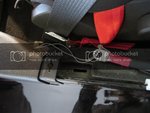
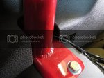
This next step was probably because I have the Cooltech Roll bar installed and the larger gusset plates restrict the space available to thread the cable into the rear seat area: I had to completely unclip the rear trim panel and slide it up vertically to route the cable to the rear seat area (REF 16 in the instructions). I used a fish wire to pull string and then then used the string to pull both cables:

IMG_0625Medium_zps4dd2b848.jpg

IMG_0626Medium_zpsbb2135eb.jpg

(If you have a roll bar installed, make sure that you push the cable as far outboard as possible to avoid crushing the cable between the trim panel and the gusset plate bolt.)

Step 5: Engine Bay wiring
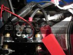
My battery leads needed to be re-routed as they were inboard of the A/C pipe and the positive cable would not reach the new terminal post. This may not be the case for you – Steve’s cables were already routed outboard. If you do need to do this, both cables have to be re-routed, even though the ground will reach. To do this you’ll need to remove the tower brace, disconnect the small ground connection to the strut tower, and then remove the Terminal Block from the positive terminal (as there is insufficient space to re-route with the Terminal Block assembled). This is what Terminal Block looks like once removed:

IMG_0629Medium_zpsd7e21e6a.jpg

Here are the cables re-routed:

IMG_0623Large_zpse71a60e2.jpg

My terminal block did need a minor modification (mentioned in the instructions) to allow the solenoid lug to fit – it’s a lot easier to do this while the block is removed. Re-attach the terminal block, and make the solenoid connections as outlined in the instructions. The positive terminal is pretty tight to the strut tower, but it fits best with the terminal vertically orientated –there’s insulation on the strut tower in addition to the rubber terminal cap, and I bent the terminal block mount back a little to increase clearance. Here’s a photo of the completed engine bay wiring:

IMG_0668Medium_zpseeeae727.jpg

Step 6: Disconnect Switch Prep (Bumper removal)
When removing the rear bumper there are also 2 push pins and 2 W-Clips that need to be removed from the lower valence (between REF 25 and REF 26 in the instructions). The W-Clips are made of brittle plastic, mine broke on removal, the replacement part number is: W790229-S900 :(

I decided to mount the switch on the Right side of the license plate (this turned out to be a good decision – the cable runs would be very tight to a switch location on the left). I marked the center of the Bumper beam and then measured the desired offset, before completing the mount, I installed the battery box and checked location of the pass through holes and cable runs (see below)

Step 9: Mount the Battery Box (I did this out of sequence compared to the instructions to make sure the positioning of the pass through holes -Step 8- was correct)
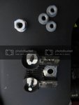
Despite several attempts, I could not get the captured nuts to collapse. The good news is you don’t need them. I drilled 5/16” holes and used regular nuts and a flat washer underneath. Just remove the 2 rear bolts and 2 front nuts retaining the Evap unit to allow it to drop 1/2" or so to get wrench access to the 2 forward holes (you don't need to completely remove the Evap unit or disconnect the harness or pipe connections). I used painters tape on the bottom of the wrench to retain each nut and washer for the forward holes:

IMG_0637Medium_zps5dd276a6.jpg


The rear Right hand hole is directly accessible:

IMG_0658_zps22be7d3a.jpg

I recommend omitting the rear Left bolt, as depending on box placement you may not have a flat surface underneath to secure to. I was fortunate and my hole lined up exactly with the gap in the reinforcing rib:

IMG_0656Medium_zpsdb24a66b.jpg

Step 8: Drill Holes for cable pass through - Straightforward

Step 7: Mount Switch Bracket
Having experienced issues with the captured nuts in mounting the Battery Box, I decided not to use them on the Bumper Bar. I positioned the bracket in the desired location, drilled ¼” holes for the bolts and then a 1” access hole in the rear bumper beam surface:

IMG_0638Medium_zps58103d09.jpg

Drilling these holes takes some patience as the bumper beam is made of high strength steel. I started the top holes with a ¼” drill and then moved to a step drill. For the access hole I started with a ½” bit and then moved to a step drill, and used cutting fluid for all the drilling. My experience was that fine tipped regular drill bits started out better and the step bits finished up better. Just take your time, as the bits will get hot very quickly.

This allowed me to install regular nuts inside the bumper beam. Again I used tape to hold the nuts in place on an offset wrench inserted through the access hole.

Step 10: Run cables – Straightforward
Here’s a photo of the switch and cables installed:

IMG_0660Medium_zps42f046d1.jpg

And inside the Trunk:

IMG_0669Medium_zpsb46a0d49.jpg

Step 11: Bumper Cover Modification
Rather than using duct tape to position the hole in the Bumper cover, I cut a 3/4” length from the tip of a steel nail and inserted in the switch shaft screw hole so that it just extends out of the shaft (without the stub shaft). I then reassembled the cover on the car and pushed the cover in the area of the nail to mark the inner surface. Using a ¼” drill, my marked location was pretty close – within 1/8”. I used a round file to open up a little and re-center and then drilled the hole to 9/16” to accommodate the stub shaft.

I also removed the tab that the license plate light harness secures to on the inside of the Bumper cover before test fitting the hole location, as my position was very close:

IMG_0645Medium_zpsc69ddd68.jpg


Here’s a photo of the completed bumper install without the license plate:

IMG_0662Medium_zps4dd49ea9.jpg

And with the Stub Shaft and knob attached: 8)

IMG_0664Medium_zps74cef7c9.jpg


I’ve just ordered a custom switch decal from Pete at Track Day Solutions and will post once it arrives……
 
367
1
Man,

Thanks for the pics. That looks to be a very well thought out kit!
Curious to know: did you use a special drill bit to drill through the bumper beam? And holy cow, how long did that take!!?
 
1,936
2,036
Exp. Level
10-20 Years
Michigan
It is a well thought out kit. Probably took about 20 minutes to drill the access hole (and about 10 minutes each for the mount holes). I used Dewalt cobalt drill bits and then the largest of these: http://www.amazon.com/gp/product/B002GQ5AKG/ref=oh_details_o09_s00_i00?ie=UTF8&psc=1

I think the cutting fluid helped -- at least keep things a little cooler -- everything gets very hot if you don't take breaks -- especially on the large access hole.
 
367
1
That's awesome!
Thanks for the updated photos!
Does the position of the switch interfere with the license plate? I can't tell from the photos.
 
1,936
2,036
Exp. Level
10-20 Years
Michigan
No -- These pics are with the license plate off. The shaft is flush with the area behind the plate with the knob and stub shaft removed, so you can mount the plate and see nothing but the plate if you position the switch correctly. Neither my Ford Racing or Battery Disconnect decals are visible with the plate mounted -- just remove the plate at the track and attach the stub shaft and the knob. I also added some thin neoprene on the back of the license plate to avoid scratching the decals.
 
My question might be stupid but...
Last time I relocated a battery in the trunk (for weight distribution and engine compartment cleanup in a 70 Boss) I did not install any solenoid. I simply installed an extra long positive cable to the trunk with a "kill switch" along and made sure my grounding was efficient.
It worked flawlessly for years...
So why all this wiring in the kit?
(I am sure I will learn something :) !!!
 

steveespo

Lord knows I'm a Voodoo Child
Moderator
4,019
1,966
Exp. Type
W2W Racing
Exp. Level
10-20 Years
Cookeville TN
patrickshelby said:
My question might be stupid but...
Last time I relocated a battery in the trunk (for weight distribution and engine compartment cleanup in a 70 Boss) I did not install any solenoid. I simply installed an extra long positive cable to the trunk with a "kill switch" along and made sure my grounding was efficient.
It worked flawlessly for years...
So why all this wiring in the kit?
(I am sure I will learn something :) !!!

Patrick
To actually kill the engine and isolate all power to the car a two pole switch is needed to shut both the battery and the alternator power from being sent to the car. If you don't shunt the alternator a few bad things will happen, the engine will keep running along with the fuel pumps AND a huge power surge will go to the ECU computer and potentially fry it. The battery acts as a capacitor and filter during engine on operation, the alternator actually provides the power. Without first disconnecting the alternator the kill swtch won't work.

When I did my relocate, I did not add a kill switch, just ran a new positive cable from the trunk to the positive cable in the engine bay, added a ground to the chassis in the trunk, grounded the negative cable in the engine compartment and added a braided ground strap from the engine block to the chassis in the engine bay. I may add a 2 pole disconnect switch later if I enter competition.
Steve
 
Hi Steveespo,
Understood.
When I did it on my old car, my switch was just meant as a battery saver or an anti-theft device, not a race kill switch to stop a running engine.
THANK YOU!
 

TMO Supporting Vendors

Buy TMO Apparel

Buy TMO Apparel
Top