The Mustang Forum for Track & Racing Enthusiasts

Taking your Mustang to an open track/HPDE event for the first time? Do you race competitively? This forum is for you! Log in to remove most ads.

  • Welcome to the Ford Mustang forum built for owners of the Mustang GT350, BOSS 302, GT500, and all other S550, S197, SN95, Fox Body and older Mustangs set up for open track days, road racing, and/or autocross. Join our forum, interact with others, share your build, and help us strengthen this community!

Vorshlag 2018 Mustang GT + S550 Development Thread

This site may earn a commission from merchant affiliate links, including eBay, Amazon, and others.

Fair

Go Big or Go Home
Supporting Vendor
277
492
Plano, TX
Project Update for December 31st, 2019: After getting caught up on some other build threads I wanted to sneak in one more forum update before the end of 2019. We have made a lot of progress on our 2015 GT project #Trigger in the last month, so I figured this would be the one to cover.
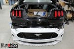
IMG_5245-S.jpgIMG_5112-S.jpg

In this post I also want to update everyone reading this build thread with more of our Phase 1 plans for this #LS550 project, as well as briefly cover a number of other shop builds we have going on at Vorshlag for 2020. I have had a lot of you question the sanity of an LS swapped S550 chassis Mustang, but if you read the section below, hopefully our logic and plans will make more sense. There's always a plan...

2020 SHOP CAR PLANS + COMPETITIONS

We have a lot going on here in the shop with customer car builds (2 of the 4 current builds shown below), new product development work, expanding our CNC and fabrication parts production capabilities, and strengthening the business. We usually have a number of project forum build threads going at any one time, including several shop owned cars built to help promote Vorshlag and expand our product portfolio. Balancing the time and budget among those shop cars and customer cars is tricky and keeps me juggling.
_D4A9641-S.jpgIMG_4828-S.jpg

In the past I've normally had one and sometimes two "development mules" that we own and build for competition, product testing, and promotion. For 2020 we're going to double down and have a total of FOUR shop development vehicles (plus another half dozen "potentials" I won't even get into). Here I will briefly list these main four and explain what each car will do for us, then we will jump into our #LS550 plans.

P8250807-S.jpgIMG_3428-S.jpg

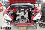
First up is this 2013 Scion FR-S we bought in August 2016 to continue development of our LS swap kit but also to test new 86 chassis related products we either make or sell. We have spent the last 2.5 years working with this car and have developed a number of parts, refined even more, and tested out many company's products - our build thread for the 86 chassis goes back to 2012. The 468" LS7 engine for this car is nearly complete at Horsepower Research (HPR) and we will install that with the intent of running this car in "street car" competitions - Optima series being chief among them. This will be Amy's primary race car and also an occasional street car for her.
IMG_3582-S.jpgIMG_4817-S.jpg

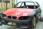
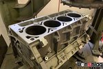
Next up is this one that the entire shop is pitching in time and money to build - this endurance race car using an E46 coupe chassis, and of course an LS swapped V8. We are almost done with the 383" / 6.3L stroker LS engine for this car, also being built at HPR. This car will be run with a wide tire, good aero, light weight, and reasonable horsepower goal.
IMG_2576-S.jpgIMG_4275-S.jpg

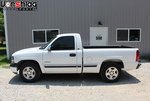
My 2000 Chevy Silverado is my second "GMT800" shop truck I've owned and I use primarily this a daily driver and parts runner. But in 2019 we stepped up things a bit and removed the tired 4.8L V8 and installed an HPR built 347" 5.7L LS engine, which immediately killed the 4L60e transmission (not a shock!) The upgraded trans and stall converter are complete and about to go in, as is the Belltech 4/6" drop kit. We are using this truck to develop a production 20x11" wheel, which fits under the stock fenders with a 315mm tire at all 4 corners (the test wheel is shown). We might do some "Pro Touring Truck" events in this one, believe it or not, and have tilt-back Sparco racing seats, full stainless headers/exhaust, and other bits already installed. Why have a boring daily driver?
IMG_1941-S.jpg2019%2003%2009-8862-S.jpg

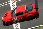
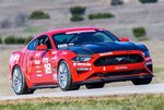
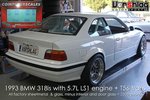
All of that is keeping us plenty busy, but none of those are the "showcase" race car that I want to promote our brand among the other top shops in the country. Both of the red Mustangs above did more to move our company forward than almost any other of the dozen plus shop cars we have built since the earliest days of Vorshlag. This recent blog post talks about our first BMW LS swap and how that build (with eleven different model chassis LS swapped to date) has helped our company grow. Sadly we only raced this car for 3 seasons (see it below left). The red 2011 Mustang (above left) was run for 5 seasons where it set 16 track records and racked up 75+ wins. The red 2018 GT (above right) was run for 2 seasons and did well enough, but mostly it helped develop and prove a lot of new products. Both of those Mustangs suffered from artificial limitations I put on them - namely keeping them full weight street cars with minimal powertrain changes. I'm ending that handicap on the #LS550 project.
e36-alpha-weight-S.jpgIMG_5109-S.jpg

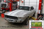
Many of you have asked why we are putting an LS into an S550, but it makes sense when you realize what we are trying to do. Take some chassis that is relatively new / current model, make it much lighter, add a lot of power, and don't hold back. That's what made our first BMW E36 LS swap work so well - it was relatively new (the E36 was only 2 years out of production when I started that build in my garage), it ended up very light, had easy power with the aluminum LS V8, giant tires, and was easy to drive. At 2508 pounds with a cage, 315mm Hoosiers, and 490 whp LS it was pretty easy to go fast. We didn't just win events, we set top times of the weekend, and ironically didn't spend a ton of money doing that. That's exactly what we want to do on the #LS550.
IMG_3113-S.jpgIMG_3136-S.jpg

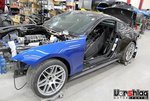
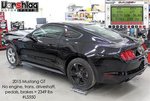
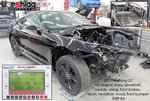
We have the relatively new chassis that effectively cost $1400, which we have taken a LOT of weight out of since - and we will continue to show weights as we go along, even though the car is not yet complete. We also didn't "take out a Coyote V8" as many like to keep stating - we bought a rolling hulk with no drivetrain and saved it from the crusher. We are installing the latest model S550 bodywork, getting a bunch of weight out, and will put in a LS V8 + big tires, big aero, big brakes, big everything. It isn't rocket science, it's just simple math. With a lot less mass to slow down/turn/speed up, we can do more with less. Or do even more with excess. And as I stated in that blog about LS swaps, we can simply make more power, more reliably, for less money with the LS engine family. That's just a reality, plus it "packages" very well.

PHASE 1 OUTLINE FOR #LS550 BUILD

As I have mentioned here previously, our black 2015 Mustang GT we are calling #Trigger is being built in two distinct phases. The first phase is to be fully LS swapped and track ready, and something that just about anyone with a reasonable budget should be able to replicate. This first phase of the build will not be a "world killer" nor will it be expensive to complete. Simple, reliable, light, and cost effective are the goals on Phase 1.

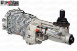
We are making everything for this car "reproducible", like the LS swap kit, suspension, wheels, drivetrain, etc. The Phase 1 engine is going to be very modest, using the 383" / 6.3L aluminum LS we are actually building for our endurance BMW E46. We will control it with a cost effective but powerful EFI system and it will be shifted manually with a strong and simple T56 Magnum XL transmission.
B61G3992-S.jpgP9121030-S.jpg

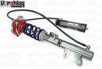
Everything else is coming from proven, leftover parts we used on our 2018 GT. Things like the differential/housing/gearing/cooler, the MCS RR2 coilovers, the wheels/tires, the brakes, the control arms, seats, and roll bar. I want Phase 1 on track SOON and then we can get onto Phase 2 shortly thereafter, which will have serious upgrades in power, grip, and aero.

DSC_1594-S.jpg76048894-978A1325-S.jpg

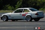
Like the early days of our BMW E36 LS "Alpha" project (above left), Phase 1 version of this #LS550 won't be pretty - just light, simple, and quick. When we have a break long enough to have the chassis spend a few weeks in "paint jail" we will have this car shot in one color, likely the same "Race Red" our 2018 GT wore. What's more important is getting it on track so we don't miss the 2020 season. I'm not going to spoil the Phase 2 plans just yet, but many of those things are already underway, and some parts are already standing by. Now let's jump into the reconstruction of this chassis and the Phase 1 upgrades starting in the section below.

continued below
 

Fair

Go Big or Go Home
Supporting Vendor
277
492
Plano, TX
continued from above

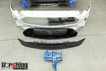
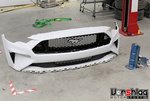
MOCK-UP 2018+ FRONT BUMPER COVER

My reasons for using the 2018-2020 GT front end are multiple - it is more aerodynamic than the 2015-17 nose, it makes the car look newer / more relevant, and I have a beautiful Anderson Composites carbon hood from our 2018 GT to use. I showed the white 2018 front plastic nose that Jason and I found at a local salvage yard last time. Shortly after posting that forum update, I heard from the folks at Parker Performance and they sold us some immaculate 2018 GT upper and lower grills at the great price!

IMG_4812-S.jpgIMG_4813-S.jpg

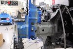
Once those arrived, using 2 sets of hands Brad and I we were able to get these popped into the floppy plastic bumper cover. This gave the front cover a lot of structure which then allowed us to mock it up on the front of the car. I also ordered a "front horn" that was cut from a 2015+ Mustang's left front frame stub (shown in blue) from eBay.

IMG_4830-L.jpg

Brad and I added a lot of wooden boards to act as a lower support just to see where this bumper cover lined up on the 2018 fenders, which themselves were added in the last segment. It all lined up perfectly and nothing else major needs to change to use the later fenders and nose on the early car. Of course we aren't using many of the OEM front end structural pieces, as we plan to make lighter versions of these.

IMG_4833-S.jpgIMG_4829-S.jpg

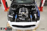
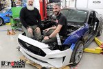
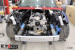
Seeing this nose installed without the upper radiator support normally use was a bit of an eye opener - there is enough room to allow both of our engineers Jason and Myles to stand in front of the engine!

IMG_4832-S.jpgIMG_4835-S.jpg

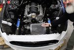
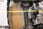
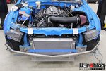
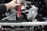
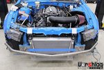
We had fun sticking things in front of the engine - like this giant trash can (vaguely turbo shaped). "So much room With 24" of distance between the front of the LS engine to the bumper cover we should have plenty of room for a rolled radiator. Should have that in next time.

REPLACE FRONT FRAME STUB

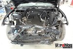
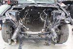
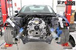
As you know from my previous posts, this 2015 GT chassis was a salvage car put together by The Parts Farm with a bunch of leftover parts, and it had a busted up front end. The damage was isolated mainly to the left front frame stub but the bumper beam was pretty trashed. The upper radiator support was hammered (which is a plastic composite piece we never planned to re-use) and the leading edge of the front lower subframe (the left lower radiator mount) was pretty bent up. We initially just cut both lower radiator mount structures off the subframe, but have since replaced the whole subframe (see section below).

IMG_3119-S.jpgIMG_3140-S.jpg

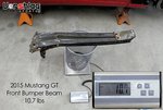
When the car arrived in late August Brad removed the mangled front bumper beam. That deformation had tweaked the mounting plate of the right front frame stub (which itself looked straight). Again, we had taken the car to our friends at Heritage and they measured everything with tram gauges - the frame rails were both straight behind the bent up section on the left front, and we checked the tweaked subframe and all of the critical sections were in spec.

IMG_3188-S.jpgIMG_4828-S.jpg

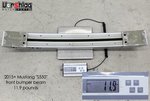
We didn't plan to just replace the OEM bumper beam but it sure would be handy to have one to line up the new frame stub. More on that later. We plann to build a tubular bumper beam like we did on this S197, shown above right. This will let us push the bumper farther forward as well as make the beam wider, for more protection of expensive bits like headlights and such in a light front hit. These S550 front headlights cost $1100/each new, and bring $450-600/each used! It is worth protecting those from a light impact with a wider bumper beam.

IMG_4980-S.jpgframe-horn-S.jpg

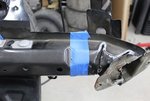
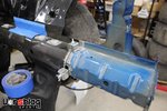
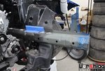
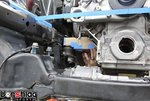
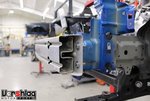
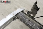
After two months of seeing this bent left front frame stub, I finally found a good "front horn" cut from a S550 Mustang, and it was time to replace this front section of our car's frame. There are accordion sections designed into the steel front frame stubs that are made to deform in a crash. This helps isolate the damage in some impacts to just the front few inches of the frame, and it is relatively easy to cut off that and weld something back on. Ford wants you to replace the whole frame in a crash, but insurance / repair jobs typically just replace the front stub with a horn - there were lots of these for sale on eBay. I marked where I wanted the cut with blue tape, just behind the damage, so only about 6" of the frame needed to be replaced. The $120 cut frame horn I bought was about 12" long, so we had lots of room to work with if I "missed the cut" on the first try.

IMG_5003-S.jpgIMG_5008-S.jpg

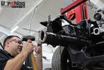
I came into the shop early one morning and started to carefully cut the frame horn with a SawsAll and a sharp, new bi-metal blade. I went slow but this did not go smoothly - the SawsAll was not the right tool for the job, and the cut was not square with my tape marks. When the crew showed up I talked with Evan and we marked a new cut, about an inch further back, and he got to work. There's a reason I hire real fabricators, heh!

IMG_5018-S.jpgIMG_5021-S.jpg

He marked both the horn on the car and lined up the same spot on the replacement frame stub, then cut them with this long die grinder with a 90 deg head and a 3" cut off wheel. He cut the stub a bit short then "snuck up on the cut" using the 12" sanding table. Sometimes you have to slow down and use the right technique to do the job right.

IMG_5023-L.jpg

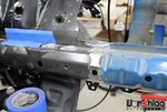
This pic above shows the alignment of the car's frame and the replacement frame horn, after Evan had cut both pieces and setup these sheet-metal clamps to hold it in place. These are handy when butt welding two thin pieces of steel together. The placement of the cut was behind the last dimple in the frame, with a round hole in the frame as the guide.

IMG_5028-S.jpgIMG_5029-S.jpg

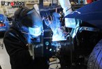
Evan then used the MIG welder and loaded with .023" ER70S wire and stitched along the cut. After the weld was completed he sanded it smooth using a tiny air powered belt sander - I missed that step in the pictures. All of this was done in about 90 minutes, so it went quickly.

continued below
 

Fair

Go Big or Go Home
Supporting Vendor
277
492
Plano, TX
continued from above

IMG_5032-S.jpgIMG_5033-S.jpg

After he was done sanding he hit the bare steel with self-etching primer and then - damned if I could see the weld. It was completely hidden. I was going to have him "plate" the seam but when he hung himself off the end of the frame and jumped up and down, it was solid.

IMG_5031-L.jpg

I know this might seem like a lot of pictures for what some would consider a simple repair, but this bent frame stub really bugged me. I had to walk by this car every day and see that janky bent piece - and now its perfect. Evan's repair work here really impressed me, and is still a bit baffling how quickly he got this done. Amazing work!

IMG_5222-S.jpgIMG_4530-S.jpg

What's crazy is he didn't have a stock bumper beam to line up the frame stub, yet he took some measurements and it lined up perfectly anyway. When we finally got our hands on a stock bumper beam (last week) Evan was able to use this to reshape and flatten the right front frame stub's mounting plate, with some gentle persuasion.

IMG_5250-S.jpgIMG_5255-S.jpg

Above is the stock 2015 bumper beam lined up and bolted to the two frame stubs of our car. Couldn't be happier with how well this turned out - a professional body shop couldn't have done it better.

IMG_5254-L.jpg

We have since replaced the entire front subframe - which we got from the same guy as the bumper beam. I will cover that in detail in another section of this post, below.

REAR SUBFRAME BUSHINGS

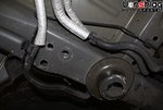
When we went to check the rear axle housing's pinion angle and it showed up at nearly 9 degrees, I knew something was wrong with the rear subframe. Brad and Even looked over the car closely, which we have since realized was haphazardly thrown together with spare parts by the place we bought the rolling chassis from. They noticed that both rear mounts of the subframe were very loose, and this allowed the pinion angle to change when it was raised up on the lift.

IMG_4542-S.jpgIMG_4543-S.jpg

I asked them drop the rear subframe to take a closer look. One subframe mounting bolt on one corner was cross threaded in the hasty reconstruction of this chassis with random parts, but Brad was able to clean up the threads and get a new bolt secured there. Sloppy work and we've seen much more of this throughout the car, but I guess I shouldn't complain about this on a $2500 chassis that we have since sold parts off of to get down to $1400.

IMG_4544-S.jpgIMG_4545-S.jpg

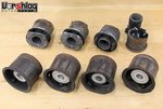
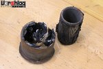
While it was out of the chassis, the 8 rubber subframe and differential mount bushings were inspected. I'm not one to recommend these bushing changes for casual HPDE use, as this is a REAL chore of a job. On this subframe with the age and neglect it has seen, it made more sense to change them. The 5 year old rubber bushings were crusty looking, but again - I don't think this will make a "lap time drop" on these relatively new S550 chassis. This is not something that will likely even "feel better" much less make the car faster - more likely it will add Noise-Vibration-Harshness (NVH), but it will remove some "void" (air) from these mounting points. And no, we won't be adding solid metal or Delrin bushings at these spots on Phase 1. Maybe... maybe in Phase 2.

_D4A0036-S.jpg_D4A0049-S.jpg

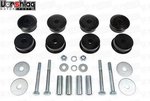
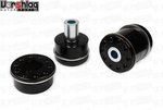
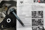
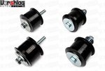
We ordered the Whiteline rear polyurethane bushings kits for both the the differential mounts (above) and the subframe mounts (shown below). These look very well made and when orientation of the bushing matters, it is clearly marked in raised letters cast into the bushing. The S550 differential bushing kit comes with new hardware, sleeves and washers as shown.

_D4A0017-S.jpg_D4A0024-S.jpg

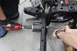
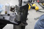
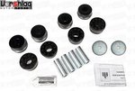
The S550 subframe mount bushings are reinforced at the mounting surfaces with steel rings and also include internal steel sleeves and washers. Now it was time to get to work removing the old bushings. THAT was the chore - removal - but installing the new bits takes only a few minutes. I made a new photo gallery showing the steps we took to get the stock bushings out of the rear subframe, and long story short: it was a a rough job.

IMG_4549-S.jpgIMG_4599-S.jpg

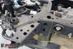
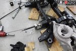
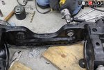
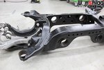
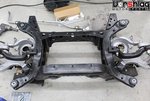
Obviously we need the entire subframe assembly out of the chassis, after which the subframe was essentially stripped to the basic steel tubular weldment. That means the control arms, shocks, uprights, diff housing and axles all came off. Maybe you don't need to take it down this far, but it gave us a LOT more access to get to the 8 bushings that needed to be pressed out.

IMG_4537-L.jpg

One extra thing we had working against us was the condition of the subframe - it had obviously been sitting in the mud for a while before it was slapped into this 2015 GT chassis. It wasn't even a subframe that came in a GT - as it had the SOLID rear brake rotors and tiniest axles (either a V6 or Ecoboost car), along with an aluminum housing super 8.8" housing (the iron housing is used in manual trans GTs and all GT350/R models). No matter, we were replacing EVERYTHING except the the big cast aluminum control arms. The steel bushings "shells" were rusted into the subframe probably far worse than normal for the age of this part, thanks to the extra harsh environmental exposure.

continued below
 

Fair

Go Big or Go Home
Supporting Vendor
277
492
Plano, TX
continued from above

IMG_4623-S.jpgIMG_4621-S.jpg

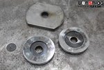
I've read the horror stories about S550 subframe bushing removal, so we "got ahead" of this by making some custom tooling - hopefully to speed things up. Myles gave me some specs, I went and bought some 4" OD steel tubing shown above, then he made some bits on the CNC plasma table to make this "receiving cup" and some pressing blanks for the other side of these differential bushings.

IMG_4628-S.jpgIMG_4636-S.jpg

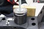
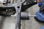
The steel tubing assembly makes a "cup" to push the diff mount bushings into, while supporting the steel subframe around the hole. The round blank pushes the bushing from the opposite side, and a threaded shaft draws them together. Honestly this should have been easier - the damn rusty bushing shells didn't help us at all.

IMG_4650-S.jpgIMG_4647-S.jpg

This was a 2 man operation that gobbled up too many hours - way longer than we expected. We have a lot of specialty tools to do this type of work and we have done it on many other cars, but the S550 bushing removal was the worst one we've tackled in ages. The rusty bushing shells were shot with penetrant and the threaded portion of the tool was tapped with a hammer between impact driving sessions, which helped them pop out of their rusty holes. A car this new should not be this difficult.

IMG_4661-S.jpgIMG_4652-S.jpg

We have a series of bushing press tools and threaded shafts as well as an expensive and large C-clamp kit we use on similar BMW bushings. We had to drill out the Ford diff mount bushing holes to a larger size to use a larger piece of all-thread, as these stuck bushing shells tore up some of the smaller shafts we have used before. Eventually we had the four diff mount bushings removed.

IMG_4639-S.jpgIMG_4666-S.jpg

The four subframe mounting bushings were even worse, as there was not enough metal on the supporting flange area around these areas to use with the pull-thru threaded bushing removal tool. We had to use the clamp method and make some other custom bits. It was a real chore.

IMG_4671-S.jpgi-MrCCGfR-S.jpg

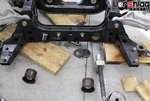
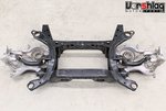
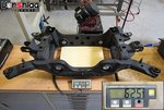
Eventually the 8 bushings and shells were removed, but our plan of making tools to help shops do this job more efficiently was just not fruitful. We had already measured the weight of the S550 rear subframe before at 62.5 pounds, so we did not weigh this one again.

i-cMxHSSb-S.jpgi-PN8wd2M-S.jpg

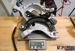
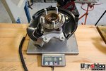
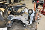
We also had these weights on the stock S550 rear suspension components (above left) and the rear uprights and hubs (above right) from previous testing.

i-6CV4JBB-L.jpg

There are a lot of bits and pieces that work together in the Independent Rear Suspension design of this S550 chassis, but that is part of the magic - and why it is inherently faster on track than the stick axle S197 Mustang. Not only does the IRS design give us rear camber and toe adjustments (that a stick axle does not have), which increased mechanical grip on track, the "dynamic geometry" and toe correction can cover up some driving flaws. It is simply easier to drive the S550 at or near the limits than the S197.

IMG_4673-S.jpgIMG_4679-S.jpg

Back to the bushing removal. Maybe if we do a few more of these jobs then make some adjustments to our S550 specific tools, it could go faster. And maybe it was just the rusty nature of these shells that made it so bad. And maybe we should have just cut these out of the subframe, like Whiteline and BMR both recommend. It would be super easy to damage the subframe with a SawsAll hacking through these bushings.

IMG_4715-S.jpgIMG_4680-S.jpg

The 8th and final bushing was very stuck - so Evan came over with an air chisel and helped cut that one out. It was noisy and very easily could have damaged the subframe, but it came out. This is not a magic solution and was still a big pain in the ass. Anyone who says this is less than a 4 hour job is lying, and you should plan for more like 8. If you are on the fence about doing this, and think you need to for performance reasons, move on to something else. This is a very high effort / low reward "upgrade". I only did this on our car to see how bad the job was, and it was worse than we feared.

continued below
 

Fair

Go Big or Go Home
Supporting Vendor
277
492
Plano, TX
continued from above

IMG_4710-S.jpgIMG_4713-S.jpg

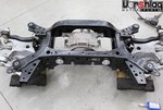
With the new bushings it is remarkably easy to install them - just do it by hand. Follow the Whiteline directions and add the grease as shown. There are no metal shells to stick into the subframe, just a solid polyurethane bushing with large washers that cover the outer edges. This setup replaces the rubber versions that have big voids of air - that will deflect under load. I will report back with how much NVH these add after we get the car on track in the spring. Brad reinstalled the subframe with the super 8.8" aluminum housing we built for the 2018 GT, with the auburn Pro diff and 4.09 gears and the cover setup for our diff cooler.

IMG_4736-S.jpgIMG_4739-S.jpg

Once it was all assembled Brad raised the subframe up into the chassis and secured it with new mounting hardware we ordered from Ford, since some of the old bits were cross threaded and crusty. The SPL arms were installed in place of the stock bits out back, as I showed last time. He also installed the Whiteline rear swaybar and the mounts we customized with grease zerks. These were easy to rotate "with pinkie finger effort" and still dead silent after 2 seasons of use on the 2018 GT, with no signs of wear. Grease zerks and proper fitting of the bushings/shells to the bar is the key here.

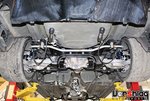
IMG_5245-L.jpg

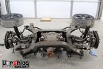
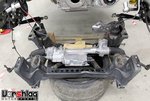
Of course our crew put everything back together as clean as possible, and the assembled rear subframe with the GT350 axles, our 4.09 diff housing, SPL Parts arms, Whiteline bar, and the MCS RR2s is shown above. We need to install the 2-piece Seals-It 3" dia grommets in the trunk floor to put the shock reservoirs inside there, for easier compression adjustments. And our diff cooler will be mounted to the spare tire well for additional testing before we make a batch of those kits. Otherwise the back of the car here is ready to go. We'll run exhaust back here soon, too.

LS / T56 SWAP TRANSMISSION CROSSMEMBER

Last time I showed the LS engine mocked up with two oil pans, and the transmission crossmember was just getting started - but when we went to go set the "down angle" of the T56 Magnum XL trans to match the "up angle" of the rear axle, it was all kinds of wrong. The pinion had nearly a 9 degree up angle!

IMG_4768-S.jpgIMG_4767-S.jpg

That is when we paused the trans mount development until we could figure out the deal with the rear subframe (see section above), which wasn't even bolted fully into the chassis from the salvage yard. With the subframe mounted correctly on new Whiteline bushings - and using this slick little flange tool that Myles made on the CNC table - we could see a pinion up angle of 3.3 degrees, which was what right in the range I expected to see (a 2-3 deg pinion angle is normal).

IMG_4779-S.jpgIMG_4784-S.jpg

With the transmission down angle set the opposite of the pinion up angle (so the U-joints on the driveshaft don't get into a harmonic battle), Myles got back to work on the transmission crossmember design. He has designed and built a number of these lately for our LS swaps using CNC plasma cut parts, from the Z4, E36 RHD, our updated E46 and the new FRS/86/BRZ version. So this S550 design followed that new style we adopted in 2019.

B61G4436-S.jpgIMG_5242-S.jpg

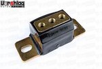
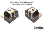
Once again we are using the proven polyurethane transmission mount bushing from Energy Suspension - which uses a captured design. We first utilized on our BMW Z4 LS swap kit in early 2019 and have moved to this for all T56 crossmember designs of late.

IMG_4781-S.jpgIMG_4783-S.jpg

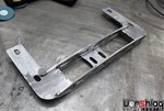
This is the production ready crossmember for our LS / T56 Magnum XL swap for the S550 chassis. The slotted and tabbed design self-aligns and will be fully TIG welded on production jigs when we make our first batch. Even with just a few tack welds it can hold up the weight of the 125 pound Magnum XL, and both exhaust and ground clearance is exceptional. The shifter lines up perfectly with the opening in the tunnel, of course. We will have these in production in a few weeks, after we verify our custom driveshaft design (which should arrive any day).

PRODUCTION LS SWAP LONG TUBE HEADERS

Now this might seem to be done out of order, as normally when we are doing an LS swap on a new chassis we make the motor mounts first, then trans crossmember, then the headers - but this time we had reasons to do everything in reverse order.

IMG_4795-L.jpg

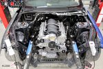
It comes down to the immense room underhood of this S550 chassis. The LS engine is so little compared to the Coyote this engine bay was designed for that we could take some liberties with engine placement to potentially shorten header development time. When headers typically take 9-12 months to go from prototype to production, I was looking to save time on this step!

IMG_4796-S.jpgIMG_4797-S.jpg

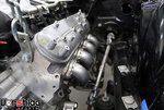
And that we did. Sending several measurements to our production header manufacturer, they were able to make something for us that fit on just the 2nd try.Huge time savings, and this is a 1-7/8" primary, proper full length header with 321 stainless bends.

IMG_4799-S.jpgIMG_4798-S.jpg

These pictures show our header design that fits this LS550 swap and uses the same design parameters (maximum ground clearance, 1-7/8" primaries, 3" collectors) - it was just easier to make this happen when we put a tiny LS in this giant car. Packaging is one of the many benefits of the LS V8 engine design over any DOHC V8 design.

continued below
 

Fair

Go Big or Go Home
Supporting Vendor
277
492
Plano, TX
continued from above

IMG_4802-S.jpgIMG_4804-S.jpg

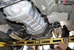
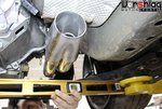
This level is placed at the lowest part of the car (the bottom of the front subframe), and that line is inches below the bottom of the headers. So unlike most long tube headers that hit the ground first, these are tucked up nicely into these two massive tunnels that Ford left us.

IMG_4795-L.jpg

So this long tube header setup is now production ready, just needs final welding. We will order a batch for inventory very soon. We can also make these with 2" primaries with little to no changes - there is just so much room in this engine bay, it is unreal. These bigger primaries will come in handy for our Phase 2 engine for sure.

LS MOTOR MOUNT DEVELOPMENT

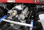
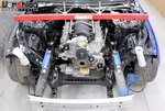
With the transmission crossmember done and headers fitted we could finalize our engine placement - which was already pretty well established. The engine was hung from a engine bay brace and we tweaked it for level, lateral and vertical placement, and kept our drivetrain angle in check.

IMG_4794-S.jpgIMG_4791-S.jpg

On this car I wanted to keep the NVH from the engine mounts to a minimum so we left the OEM engine mounts in the front subframe. This will work great for street cars, and there are already poly and all metal engine mounts that work with the stock Coyote V8 that can be swapped in place. We have used some of the aftermarket choices for the stock mounts and were a bit underwhelmed - so this will give us an excuse to make a Vorshlag poly and Nylon engine mount kit that works with the S197 andS550 Coyote V8s, as well as our LS swap kits for both chassis.

IMG_4793-S.jpgIMG_4808-S.jpg

The uniquely high placement of the stock engine mount makes for a nearly horizontal piece that needs to go from the block to the chassis. Space gets a little tight around the front header tubes but nothing we cannot design around.

IMG_4912-S.jpgIMG_4911-S.jpg
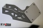
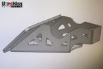
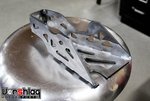
Our tubular LS motor mounts are one of our most time consuming items to make and our engineering team (me, Jason, Myles) have been talking about a CNC cut and bent plate steel design for some time. We made some test units for another chassis but this horizontal design might lend itself to this style more easily. After we talked about the design Myles drew up something in CAD, then cut one in card board to test the fit.

IMG_4846-S.jpgIMG_4930-S.jpg

That part looks good so he tweaked the CAD design, cut one out on the CNC table, bent it to shape then tack welded it together. The production mounts will be fully seam welded, of course. We still had a few iterations of revisions to make yet.

IMG_4932-S.jpgIMG_4933-S.jpg

This looked good in the car mocked up to the engine-side plate, but then we needed to install these with headers and check for clearance to the front primary tubes.

IMG_5153-S.jpgIMG_5154-S.jpg

A little more welding and these would be good to go - but Myles is working on a final revision to these LS mounts and we should have a production ready version of them ready in early January 2020.

IMG_5191-S.jpgIMG_5192-S.jpg

BRAKE & PEDAL BOX INSTALL + DASH WEIGHTS

While all of the LS swap design work was going on I asked Brad and Evan to take out the stock dash and get many of the missing parts I had ordered installed. I also felt like there was some weight to be saved in the dash - which I wanted to keep and finish off, at least the outer shell.

IMG_3914-S.jpgIMG_2389-S.jpg

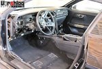
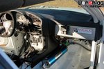
When we bought the car (shown above) the dash had already been stripped of anything of value - the gauges, trim panels, radio and virtually all of the wiring. The dash had been out but then slapped back into the car hastily with many of the bolts missing. We could shake the dash and it was barely held in on one side.

continued below
 

Fair

Go Big or Go Home
Supporting Vendor
277
492
Plano, TX
continued from above

IMG_5035-S.jpgIMG_5034-S.jpg

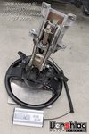
First the steering column was removed, which was also barely held in place. This had been out of the car, stripped of the airbag and some other bits, and shoved back into the car quickly. The splined slip joint under the dash was somewhat mangled and jammed together, so that had to be repaired before it would go back in place. I want to keep the factory tilt / telescoping column, as it is relatively lightweight (12.7 pounds), has a rigid cast aluminum structure, and the ergonomics of this fit me in this car well. Not enough weight there to chase something that will lose adjustments and likely even some rigidity.

IMG_5044-S.jpgIMG_5046-S.jpg

The dash is held in place on the sides of the A-pillar sections as well as this lower bracket, that we removed. Pieces like this will be replaced with much thinner aluminum brackets that way 1/4 as much.

IMG_5041-M.jpgIMG_5038-M.jpg

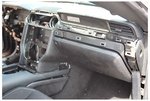
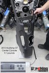
We then got a weight of this semi-stripped dash assembly, which was 50.7 pounds. There is a lot of weight in there that we can whittle down, including an airbag that is part of the glove box. The center console was just sitting in the car when we got it, but it weighs in at only 9.1 pounds. We will likely reinstall that for the Phase 1 build, as well as the lightened dash. I just like a little more completeness in the interior of a car, even a race car.

IMG_5045-S.jpgIMG_5049-S.jpg

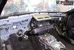
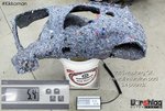
With the dash out of the way the sound insulating pad at the firewall was removed, along with the HVAC box. This insulation pad will not go back in and sheds 5.4 pounds in the process.

IMG_5047-S.jpgIMG_5056-S.jpg

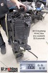
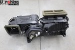
Last up is the HVAC box - which is the heater core, evaporator core for the air conditioner, blower motor, and complicated duct work buried under the dash. This 22.5 pound box (without the coolant that the heater core holds) will not go back in either. Instead we will use the 6.5 pound lightweight defroster box we normally put into race cars. This keeps a heater core and blower motor in a more compact box to blow on the windshield on cold race days. All told these pieces above weigh in at 102 pounds, and I suspect we will reinstall the steering column, center console, a gutted dash, and a lighter heater box.

IMG_4016-S.jpgIMG_4017-S.jpg

Didn't weigh the missing but lightweight dash trim pieces, which ironically I bought on eBay from The Parts Farm (they could have come off this same car). If we can cut that total interior weight number down by 40 to 50 pounds that will be a nice accomplishment - while still keeping a fully functional/adjustable steering column, a visually complete dash, and a working heater in the car. I will show those lightening steps and weights going back in on a future post.

IMG_3988-S.jpgIMG_5053-S.jpg

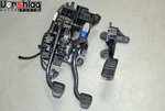
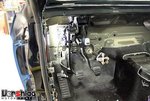
This car was missing the pedals, brake booster, brake master, and more. I bought this used OEM pedal box from a 2016 Mustang GT online for $124, and it even came with the Mustang electronic throttle pedal (which we might not use, depending on which EFI system we go with). The pedal box was bolted in with the dash out of the way, then the brake booster went in from the firewall side.

DSCN0048-S.jpgIMG_5052-S.jpg

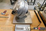
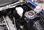
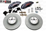
We ordered a new brake booster and PP1/PP2 style master cylinder from Ford, which we also sell on our website. The master cylinder is indeed designed with a very different hydraulic ratio than the base GT/V6/Ecobooster master, which we found out the hard way when we upgraded our 2018 GT to the PP1 brakes. I was never convinced that the brake booster we bought for our 2018 GT was in any way different but it did have a different part number. The 2015-17 GT used the same booster for PP1 and base brakes, so we bought that model.

DSCN0052-S.jpgB61G5247-S.jpg

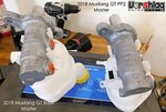
I am not going to re-hash what was already posted in this thread earlier, but long story short: there is a reason why we include the PP1 master cylinder with the 6 piston Brembo 15" brake upgrade kit we sell. It will NOT work on track without the correct hydraulic ratio master, and the difference is easy to measure and see.

continued below
 

Fair

Go Big or Go Home
Supporting Vendor
277
492
Plano, TX
continued from above

IMG_5075-S.jpgIMG_3983-S.jpg

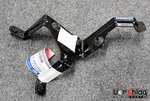
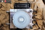
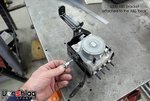
The salvage yard of course removed the ABS controller and bracket, so I bought a PP1 ABS unit online for $64 and then bought a new bracket from Ford for a whopping $18. Sure we could have made a bracket, but why? This is a nicely made, fully isolated bracket for this chassis and this ABS brick, and installation took minutes.

IMG_5217-S.jpgIMG_5274-S.jpg

Sometimes the real trick is learning when it makes since to build something custom vs buy something new that is made for the job. We have most of the brake hard lines that will be routed and secured after the subframe swap is done, and the front flex lines are on the Powerbrake kit. We're making rear flex lines for the upgraded rear brakes, which I will show later.

REAR BRAKE "UPGRADE" + NEW FORD RACING HUBS

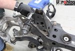
With so much of this car's existing parts being "iffy" we decided it would be smart to upgrade both the front and rear hubs with the ford Racing versions we sell. These come with longer and stronger ARP wheel studs, which can be very handy, and the new hubs will give us fresh Ford bearings to start with.

IMG_4721-S.jpgIMG_4704-S.jpg

These hubs are relatively easy to install in the rear - and since we had the rear subframe and axles being swapped anyway, this wasn't a lot of extra work.

IMG_5054-S.jpgIMG_5110-S.jpg

The work up front is also pretty straightforward. With the front brakes out of the way the main center nut was removed, the new hubs swapped on, and the nut torqued to 250 ft-lbs. The ARP studs are much longer at both front and rear, which will show the tech inspectors what they want to see - fully engaged open lug nuts at each hole.

IMG_5279-L.jpg

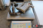
I did get some weights on the old sliding single piston rear caliper and and bracket - shown above - but I forgot to weigh the solid or vented rotors. It's all cast iron stuff so it is a bit on the heavy side.

_D4A0117-S.jpgIMG_5252-S.jpg

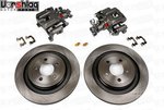
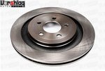
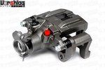
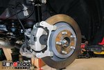
The rear brakes that came on our 2015 were from the LOWEST base, base model solid disc version, shown earlier. These brake discs were rusty and non-vented, so we put together our S550 "Rear brake upgrade kit" using Stoptech 13" rotors and the associated calipers + brackets needed. This rear kit makes it easier for owners of these base model V6/Ecoboost cars to upgrade to PP1/GT level brakes out back, and with our front Brembo 6-piston brake kit they can have matching PP1/GT front brakes and master cylinder as well.

_D4A0113-S.jpgRear_S550-S.jpg

This kit consists of new 13" vented GT rear rotors and new calipers and mounting brackets made for the thicker vented rotor. These are actual pictures of the parts that come in our rear GT brake upgrade kit - and could also be used to refresh your GT rear brakes if they are looking pretty haggard from track abuse. Some might think it strange to use the inverted hat GT rear rotors on #Trigger, but you know what? They worked pretty dang well on the back of our 2018 GT for 2 seasons of track and autocross use. Did they get hot? Oh yes, we logged 800°F rear rotor surface temps. But we still only used one set of rotors and G-LOC pads on the back of that car for 2 full seasons, and they still have life left.

DSCN1413-S.jpg76048894-978A1325-S.jpg

We logged 1.5g stops on Hoosiers and 1.4g stops on "street" tires, so these bits weren't holding us back. Of course we would like to be able to have rear rotors that can be actively cooled, so we will work on making a "normal" 2-piece rear rotor for the S550 at a later date. For now, this should be fine for Phase 1 of our #LS550 build.

FRONT SUBFRAME REPLACEMENT

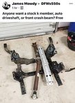
The front subframe was bent in two ways on the car we bought, as I have outlined before. But the critical points measured out OK, so this was going to be ignored to save time and money for other parts of the build. Then a free OEM S550 front subframe and bumper beam popped up on a local S550 Mustang FB group... well I could not ignore that price!

IMG_E6583-S.jpgIMG_5221-S.jpg

I managed to go pick up these parts last week, and to my surprise, it was all in perfect shape - just like he said. Big thanks to James Mowdy for the hookup on these parts! Major peace of mind knowing this bent unit will be out of our car.

IMG_5224-S.jpgBMR-S550-subframe-drag-race-S.jpg

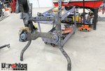
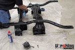
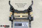
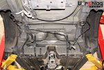
After we unloaded this 58.2 pound stock subframe, Brad soaked it in WD40, which loosened up any residual grease and grime. After an hour of soak the muck was wiped off, then it looked as good as new. Not a ding or scratch on it, which is amazing since this is the lowest part of the chassis.

continued below
 

Fair

Go Big or Go Home
Supporting Vendor
277
492
Plano, TX
continued from above

IMG_5230-L.jpg

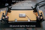
Yes there are lighter tubular aftermarket S550 subframes versions out there, but those are more suited for drag racing than a road race car. Most of the suspension and braking loads pass through this welded assembly, which also holds the engine, steering rack, and swaybar and their loading. When it is released we will check out the tubular front BMR road race version and see if it makes sense for Phase 2. Their drag race version drops 30 pounds but I wouldn't turn a corner with that thing on a bet.

IMG_5227-L.jpg

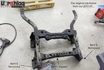
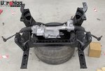
Once the "new" subframe checked out Brad dropped out the old and busted unit. The SPL front lower control arms were unbolted, the steering shaft was disconnected from the EPAS rack, and the 8 subframe bolts were removed. Some of these bolts were replaced and the holes in the chassis were cleaned up with a thread chaser.

IMG_5228-S.jpgIMG_5238-S.jpg

Once the old subframe was removed the right front frame stub "relaxed" a fraction of a fraction of an inch, so there was still some stress being held in place from the accident that totaled this car. With this subframe sitting on the shop floor, the EPAS steering rack was removed and swapped over to the new subframe. Man I'm so glad this part showed up because I was reluctant to spend $900 on a new one when a good, used OEM unit like this would do. Just needed some patience and good luck.

IMG_5235-L.jpg

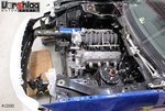
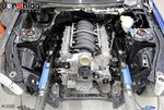
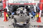
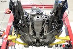
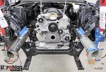
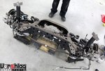
Got a few shots of the underside of the engine bay with the subframe out of the way. The LS engine is hung from the engine bay brace and the trans is bolted into the crossmember we built.

IMG_5232-S.jpgIMG_5234-S.jpg

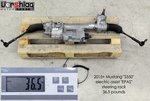
We weighed the electric power assist "EPAS" rack while it was out of the old subframe, then swapped it over to the "new" one. Everything lined up perfectly.

IMG_5240-S.jpgIMG_5286-S.jpg

The subframe was reinstalled and everything was torqued to spec with the new hardware. The bumper beam was then bolted to the front frame stubs, which lined up perfectly. This "correct" OEM subframe will now allow us to use the lower radiator mount bushings in the front subframe extensions (that we had to cut off the old, bent unit), which should work great with a rolled custom radiator install. I will show the radiator install in a future post.

ELECTRICAL WORK: FULL CHASSIS REWIRE

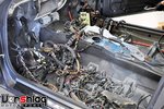
Like everything else on this chassis, the electrical harness was removed. Like - the whole damn wiring harness and fuse box are gone. There was only a little wiring left, like the ABS sensors at the hubs. All of the dash, engine bay, lighting, and chassis wiring is gone. The X-Y axis yaw sensor was still on the transmission tunnel, so I guess they forgot to grab that.

DSC_4881-S.jpgDSC_5022-S.jpg

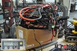
As we delve into the wiring on our 2015 Mustang GT I wanted to show typical chassis wiring harness weights and our "race car" harness solutions. The 49.4 pound weight shown above is a typical OEM chassis harness from a modern BMW, which is not too different from other cars we work on. Nearly 50 pounds of CAN integrated madness, and that's not anything in the engine bay either - just the chassis. Sometimes a bunch of this copper is hidden under the carpet, behind the dash, but it is everywhere - like a plague!

DSC_6758-S.jpgDSC_7359-S.jpg

Old OEM wiring can really let you down as it ages - breaks in the plastic insulator casing can cause shorts, the wire itself can get brittle and break, excess weight and mess, etc. I'm not saying we have never built race cars with OEM wiring - we have, and it always sucked up a lot of time, and the wiring looked like ass. Instead of spending dozens of hours cutting circuits out of a harness and repairing broken or damaged wiring for a LS swapped dedicated race car, we would rather replace it with a new harness

continued below
 

Fair

Go Big or Go Home
Supporting Vendor
277
492
Plano, TX
continued from above

IMG_5280-S.jpgIMG_5281-S.jpg

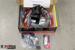
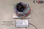
Something like this one from Painless Performance Products. Making a harness from scratch takes a LOT of time and can gobble up a lot of money. This 21 circuit harness is brand new, uses GM color coding, and weighs in at 7.6 pounds... and we will cut some of this away. This one cost $249 and was made right here in Ft Worth, Texas. It is going into our 2015 Mustang starting next week.

IMG_5284-L.jpg

Of course some racers can be "wiring snobs" and will brag about a $20K custom chassis harness they had built. It won't make their car one bit faster or slower - it comes down to reliability and weight, and of course cost. Where else could that $20K be spent to make the car faster? We have used these Painless chassis harnesses on a number of race car builds and the clocks don't care that they didn't get Raychem heat traced / custom labeled / IP67 sealed / custom chassis harnesses with PDM boxes and all of that. We aren't building F1 cars here.

Deutsch-Solid-Terminals-kit-S.jpgIMG_3401-S.jpg

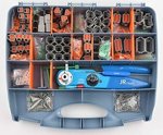
We do go the extra mile and use better Deutsch connectors and pins on any junctions we have to add, but often we will use the OEM connectors and a length of wiring from the stock bits we are trying to connect to (if they are in good condition). It is not uncommon to spend more on the Deutsch connectors than the Painless chassis harness. Things like the headlights, tail lights, windshield wipers, and a select few things will either get a "pigtail" cut from the OEM harness and spliced into our Painless harness, or new OEM style plugs with pins crimped onto the Painless harness. Non-stock things like the motorsports heater box fan motor will get a Deutsch connector.

DSCN0629-S.jpgIMG_0309-S.jpg

We are not unaccustomed to a "total rewire" of a car, and in fact it generally solves a lot of problems on chassis more than a ten years old. The E46 M3 (above left) has the Painless fuse box mounted to a panel under the false floor on the passenger side. The LS3 powered, tube framed 69 Camaro (above right) has the Painless fuse box mounted to the transmission tunnel, per the customer's request (easy access, like modern Trans Am race cars). We will likely add the one to our #LS550 under the hood, where there are acres of room.

IMG_3906-S.jpgIMG_4848-S.jpg

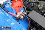
For power distribution we will use another 3-pole Bussman block with 100 to 150 amp fuses, like we used on this Gen II Coyote swapped 2010 Mustang above. This helps take the feed from the battery (and the solid state Cartek battery isolator we will install) and feeds it to the fuse box, starter, EPAS rack and other high amp circuits

IMG_4842-S.jpgIMG_4838-S.jpg

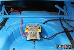
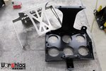
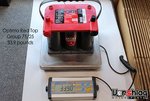
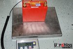
Lastly the battery will be another Group 75/25 Optima yellow top AGM battery mounted with one of our production 2-piece battery trays. We have used this battery setup on 3 cars recently and each time it "fixed problems".

IMG_2989-S.jpgDSC_7067-S.jpg

Sure, this is a 20 pound jump over the golf kart sized Odyssey PC680 AGM we used to put in a lot of cars in the past. But as we've seen, modern cars have enough drain that they tend to kill a little PC680 in a matter of only a few days. I cannot count how many times we have had to push a car with a dead PC680, but that hasn't happened with anything sporting the larger Optima units. The Group 75/25 is the lightest Optima they make, a solid 10 pounds lighter than some other group sizes. Dead batteries have cost me too many hours of frustration, lost track sessions, and I have had enough of that nonsense. We will find that 20 pounds elsewhere.

WHAT'S NEXT?

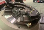
At the 2019 PRI show show we talked to a number of vendors who have seen this #LS550 build and want to work with us to test some of their products. Tilton had reached out before the show. We looked at their new Tilton ST-246 twin disc clutch in person, and it was impressive. Its lighter than a stock clutch and flywheel, of course it is still Tilton, but not "stupid light" setup that you stall every time you try to move the car. With two full sized sprung hub discs of two material choices, it can hold 850 or 1250 ft-lbs of torque. We will use one of these in both our 86 and the #LS550, and it should work well for us on Phase 2 engine.

IMG_6466-S.jpgIMG_5257-S.jpg

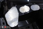
Evan made some templates for firewall openings we need to cover, and Myles cut them out on the CNC plasma table. If these turn out as nice as I hope we will sell these as a kit to other S550 race car builders. We have a lot more going on but I won't bore you with more speculation - mostly I wanted to cover what we have done in the month since my last post.

Thanks for reading, and have a happy 2020!
 
Hello Terry Fair,

I own a 2018 GT EU MT, so it has the PP.
One lap on the Nürburgring, and it overheats:

I changed:
Mishimoto Oil Cooler
Mishimoto Radiator
170°F Thermostat

But still overheating. Have you changed your cooling system?
 

Fair

Go Big or Go Home
Supporting Vendor
277
492
Plano, TX
Hello Terry Fair,

I own a 2018 GT EU MT, so it has the PP.
One lap on the Nürburgring, and it overheats:

I changed:
Mishimoto Oil Cooler
Mishimoto Radiator
170°F Thermostat

But still overheating. Have you changed your cooling system?
I don't know the EU models well, but if your car has the electronically controlled "grill shutters" remove that. If you have the Mishi oil cooler, that cannot fit with the shutters in place so that's a wash.

You already have the typical fixes we recommend: the bigger radiator and oil cooler.

The Green Hell is a tricky track and there are huge portions that keep your mind very busy. One thing you might keep an eye on is your RPMs. A lot of times when I right seat / instruct with HPDE students I have to keep reminding them to UPSHIFT.

It is easy to leave the manual "stuck in a gear" and just keep the revs buried at the top end, especially at the 'Ring with those complicated sections that have a lot of esses, hills, or other "busy" stretches where you don't have time to shift, or your speeds are somewhat constant.

The Coyote V8 engine doesn't like to "rev high" any better than any other engine. Sustained high RPM use can cause excecessive heat, which will raise coolant temps, oil temps, etc. Try some of those busy sections in the next higher gear and see what it does to coolant temps.

EDIT: OK, just noticed your YouTube video and watch it. That was fun! Some comments:

1. Your driving is great. Seriously, most of the 'Ring videos I see the people are crawling or driving way above their head. You are doing neither.
2. Distractions to remove: FUZZY DICE, turn off the Sat Nav screen. The optional electornic dash is REALLY nice though.
3. I only saw a few occasions where you "held a gear" and let it rev a bit. Not bad.
4. Many of your upshifts were above 7150 rpms.

Try making a lap with all upshifts at or below 6200 rpm. That 1000 rpm lower shift threshold might fix all of the heating issues.
Cheers,
 
Last edited:

Bill Pemberton

0ld Ford Automotive Racing Terror
8,405
8,333
Exp. Type
Time Attack
Exp. Level
20+ Years
Blair, Nebraska
Vell, das ist richtecht , Vorschlag ist eine recommendation ( English Translation) , so perfect company to ask a question and buy their product if mein haus bin aus Deutschland!
 
7
7
Exp. Type
HPDE
Exp. Level
Under 3 Years
Mexico City
"these cars will FUEL STARVE BADLY on a road course in left hand turns, so we almost never let this Mustang get below 1/2 tank of fuel"
How can I fix this?
I realized and came with same solution as you, I have to re-fill the tank when gets to 1/2 level...
Is there a thread about this? which options are out there?

Can you post the list of Base Parts Number for the PP2L Splitter setup?
 

boardkat

CAMtard
131
179
Exp. Type
W2W Racing
Exp. Level
10-20 Years
Lake Oswego, OR
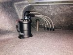
hydramat, fuel foam on the hump, etc aren’t big enough bandaids; you will still fuel starve on CCW configs under 1/2 tank, especially as you go up in power and/or switch to E85. plumbing in a fuel surge tank fixed all my problems:

DB95A423-A075-43B3-9E57-DC57907E1543.jpeg
 
Last edited:

TMO Supporting Vendors

Latest posts

Buy TMO Apparel

Buy TMO Apparel
Top